RM2040EQ
_51
Engine / Hybrid System
_014692
HYBRID / BATTERY CONTROL
_0074886
HYBRID BATTERY SYSTEM
U
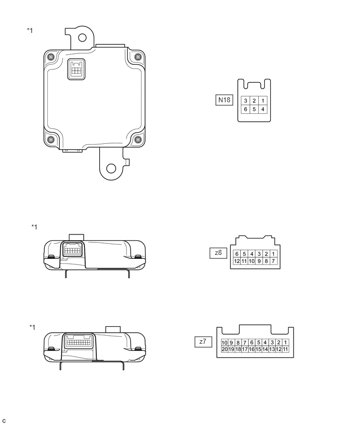
HYBRID / BATTERY CONTROL HYBRID BATTERY SYSTEM TERMINALS OF ECU
4.385,5.177 4.74,5.396
0.354,0.219
4.51,1.979 4.865,2.198
0.354,0.219
4.073,7.031 4.427,7.25
0.354,0.219
0.563,0.552 0.813,0.771
0.25,0.219
10
false
*1
0.615,6.75 0.865,6.969
0.25,0.219
10
false
*1
4.49,5.188 4.719,5.333
0.229,0.146
10
false
z8
4.563,2 4.854,2.146
0.292,0.146
10
false
N18
4.167,7.042 4.344,7.188
0.177,0.146
10
false
z7
0.656,4.656 0.906,4.875
0.25,0.219
10
false
*1
| *1 | Battery Smart Unit | - | - |
| Terminal No.
(Symbols) |
Wiring Color | Terminal Description | Condition | Standard (V) |
|---|---|---|---|---|
| z8-2 (TB2) - z8-8 (GB2) | B - B | Battery temperature sensor 2 | HV battery temperature: -40 to 90 °C (-40 to 194 °F) | 4.8 (-40 °C (-40 °C)) to 1.0 (90 °C (194 °F)) |
| z8-3 (TB1) - z8-9 (GB1) | W - W | Battery temperature sensor 1 | HV battery temperature: -40 to 90 °C (-40 to 194 °F) | 4.8 (-40 °C (-40 °C)) to 1.0 (90 °C (194 °F)) |
| z8-4 (TBO) - z8-10 (GBO) | R - R | Battery temperature sensor 0 | HV battery temperature: -40 to 90 °C (-40 to 194 °F) | 4.8 (-40 °C (-40 °C)) to 1.0 (90 °C (194 °F)) |
| z8-5 (IB) - z8-12 (GIB) | Y - B | Current sensor | Power switch on (READY) | 0.5 to 4.5 |
| z8-6 (VIB) - z8-12 (GIB) | BR - B | Power source for battery current sensor | Power switch on (IG) | 4.5 to 5.5 |
| N18-3 (IGCT) - N18-6 (GND) | R - W-B | Control signal | Power switch on (READY) | 11 to 14 |
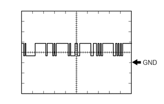
| N18-1 (BTH+) - N18-6 (GND) | B - W-B | Serial communication | Power switch on (IG) | Pulse generation
(waveform 1) |
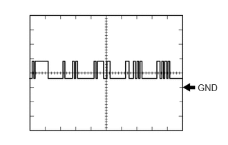
| N18-4 (BTH-) - N18-6 (GND) | W - W-B | Serial communication | Power switch on (IG) | Pulse generation
(waveform 2) |
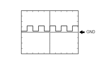
| N18-5 (FP0) - N18-6 (GND) | V - W-B | Battery cooling blower No. 0 monitor signal | Cooling blower activated | Pulse generation
(Waveform 3) |
| Cooling fans not operating | 4.5 to 5.5 V | |||
| N18-6 (GND) - Body ground | W-B | Ground | Always (continuity check) | Below 1 Ω |
Oscilloscope waveforms
- HINT:
-
Oscilloscope waveform samples are provided here for informational purposes. Noise and fluttering waveforms have been omitted.
a.
2.99,1.229 3.396,1.427
0.406,0.198
10
false
GND
Waveform 1
| Item | Content |
|---|---|
| Terminal | N18-1 (BTH+) - N18-6 (GND) |
| Equipment Setting | 2 V/DIV., 500 μs/DIV. |
| Condition | Power switch on (IG) |
- HINT:
-
The waveform will vary depending on the content of the digital communication (digital signal).
b.
2.979,1.24 3.375,1.479
0.396,0.24
10
false
GND
Waveform 2
| Item | Content |
|---|---|
| Terminal | N18-4 (BTH-) - N18-6 (GND) |
| Equipment Setting | 2 V/DIV., 500 μs/DIV. |
| Condition | Power switch on (IG) |
- HINT:
-
The waveform will vary depending on the content of the digital communication (digital signal).
c.
2.969,1 3.385,1.448
0.417,0.448
10
false
GND
Waveform 3
| Item | Content |
|---|---|
| Terminal | N18-5 (FP0) - N18-6 (GND) |
| Equipment Setting | 5 V/DIV., 1 ms/DIV. |
| Condition | Battery cooling blower assembly operating (Active Test of cooling fan being performed) |
- HINT:
-
The wavelength will vary with the operating speed of the battery cooling blower assembly.