STEERING COLUMN STEERING COLUMN ASSEMBLY INSPECTION
CAUTION / NOTICE / HINT
- NOTICE:
-
When using a vise, do not overtighten it.
PROCEDURE

 1.INSPECT PRELOAD
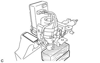
| *1 | Aluminum Plate |
| *2 | Wooden Block |
Secure the steering column assembly in a vice using aluminum plates as shown in the illustration.
- NOTICE:
- ·
Do not overtighten the vice, as the steering column assembly may become deformed.
·Support the steering column assembly with a wooden block or similar item to ensure that it does not fall.
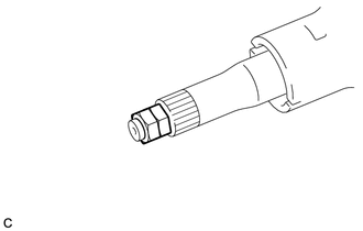
| *1 | Service Nut |
Install the 2 service nuts to the steering main shaft.
- Recommended service nut:
- Thread diameter:
12.0 mm (0.472 in.)
- Thread pitch:
1.25 mm (0.0492 in.)
Simultaneously rotate the service nut that was installed first counterclockwise and rotate the service nut that was installed second clockwise to lock them.
- NOTICE:
-
Do not apply excess torque to the service nuts by using a tool such as an impact wrench.
- HINT:
-
These nuts are installed to turn the steering main shaft. They should be removed after inspecting the steering main shaft rotating torque.
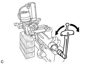
Using a torque wrench, turn the main shaft and measure the preload.
- Preload:
1.2 to 1.7 N*m (12 to 17 kgf*cm, 10 to 15 in.*lbf)
If the preload is not as specified, replace the electric power steering column sub-assembly with a new one.