DOOR LOCK REAR DOOR LOCK INSPECTION
PROCEDURE

 69060A
1.INSPECT REAR DOOR LOCK WITH MOTOR ASSEMBLY LH
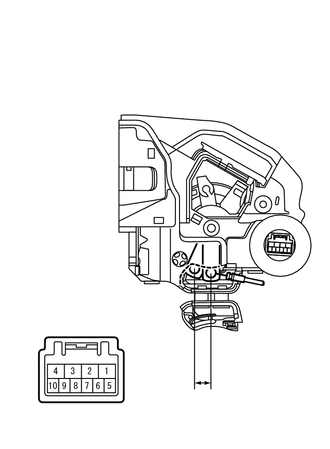
| *a | Component without harness connected
(Rear Door Lock with Motor Assembly LH) |
| *b | Unlock |
| *c | Lock |
Check the operation of the door lock motor.
Apply auxiliary battery voltage and check the operation of the door lock motor.
- OK:
Connection Result Auxiliary battery positive (+) → Terminal 4 (L)
Auxiliary battery negative (-) → Terminal 1 (UL)Locks Auxiliary battery positive (+) → Terminal 1 (UL)
Auxiliary battery negative (-) → Terminal 4 (L)Unlocks
If the result is not as specified, replace the rear door lock with motor assembly LH.
| *a | Component without harness connected
(Rear Door Lock with Motor Assembly LH) |
| *b | Unlock |
| *c | Lock |
Check the operation of the unlock detection switch.
Measure the resistance according to the value(s) in the table below.
- Standard Resistance:
Tester Connection Condition Specified Condition 6 (LSSR) - 9 (E) Locked 10 kΩ or higher 6 (LSSR) - 9 (E) Unlocked Below 1 Ω
If the result is not as specified, replace the rear door lock with motor assembly LH.
69050A
2.INSPECT REAR DOOR LOCK WITH MOTOR ASSEMBLY RH
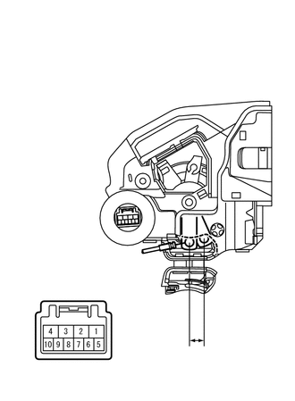
| *a | Component without harness connected
(Rear Door Lock with Motor Assembly RH) |
| *b | Unlock |
| *c | Lock |
Check the operation of the door lock motor.
Apply auxiliary battery voltage and check the operation of the door lock motor.
- OK:
Connection Result Auxiliary battery positive (+) → Terminal 4 (L)
Auxiliary battery negative (-) → Terminal 1 (UL)Locks Auxiliary battery positive (+) → Terminal 1 (UL)
Auxiliary battery negative (-) → Terminal 4 (L)Unlocks
If the result is not as specified, replace the rear door lock with motor assembly RH.
| *a | Component without harness connected
(Rear Door Lock with Motor Assembly RH) |
| *b | Unlock |
| *c | Lock |
Check the operation of the unlock detection switch.
Measure the resistance according to the value(s) in the table below.
- Standard Resistance:
Tester Connection Condition Specified Condition 6 (LSSR) - 9 (E) Locked 10 kΩ or higher 6 (LSSR) - 9 (E) Unlocked Below 1 Ω
If the result is not as specified, replace the rear door lock with motor assembly RH.