RM2040EQ
_58
Vehicle Interior
_014723
THEFT DETERRENT / KEYLESS ENTRY
_0075055
THEFT DETERRENT SYSTEM
U
THEFT DETERRENT / KEYLESS ENTRY THEFT DETERRENT SYSTEM TERMINALS OF ECU
CHECK MAIN BODY ECU (MULTIPLEX NETWORK BODY ECU) AND INSTRUMENT PANEL JUNCTION BLOCK ASSEMBLY
a.
Disconnect the main body ECU (multiplex network body ECU) connectors.
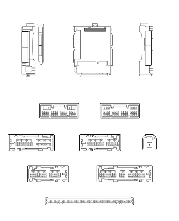
2.229,3.771 2.552,3.979
0.323,0.208
5.833,5.01 6.156,5.219
0.323,0.208
3.906,5.031 4.229,5.24
0.323,0.208
1.125,5.01 1.448,5.219
0.323,0.208
1.781,6.292 2.104,6.5
0.323,0.208
4.927,6.292 5.25,6.5
0.323,0.208
3.417,7.531 3.74,7.74
0.323,0.208
4.688,3.771 5.01,3.979
0.323,0.208
4.031,1.135 4.031,0.854
4.031,0.854 4.146,0.854
false
1.677,1.99 1.938,1.99
false
1.677,1.552 1.938,1.552
false
1.479,1.552 1.573,1.552
false
1.479,1.99 1.573,1.99
false
1.479,3.198 1.479,1.542
false
1.615,0.958 1.615,0.688
1.615,0.688 1.708,0.688
false
3.479,7.552 3.979,7.896
0.5,0.344
10
false
MB
5.917,5.031 6.417,5.406
0.5,0.375
10
false
3F
1.198,5.021 1.74,5.385
0.542,0.365
10
false
3C
1.865,6.313 2.219,6.531
0.354,0.219
10
false
3B
5.01,6.313 5.385,6.583
0.375,0.271
10
false
3A
3.979,5.052 4.406,5.313
0.427,0.26
10
false
3D
4.75,3.792 5.146,4.115
0.396,0.323
10
false
I13
2.302,3.792 2.604,3.979
0.302,0.188
10
false
I12
5.865,2.198 6.521,2.531
0.656,0.333
10
false
3A
1.979,1.927 2.469,2.26
0.49,0.333
10
false
I12
1.979,1.479 2.385,1.74
0.406,0.26
10
false
I13
0.906,2.094 1.438,2.396
0.531,0.302
10
false
3D
1.073,2.688 1.521,2.938
0.448,0.25
10
false
3F
0.906,1.49 1.323,1.792
0.417,0.302
10
false
3C
5.865,1.469 6.344,1.75
0.479,0.281
10
false
3B
4.198,0.781 4.792,1.115
0.594,0.333
10
false
MB
0.25,0.167 0.771,0.531
0.521,0.365
10
false
*A
1.417,3.198 1.802,3.479
0.385,0.281
10
false
*2
1.76,0.625 2.26,0.917
0.5,0.292
10
false
*1
| *A | Main body ECU (multiplex network body ECU) with 2 connectors | - | - |
| *1 | Main body ECU (multiplex network body ECU) | *2 | 2 connectors |
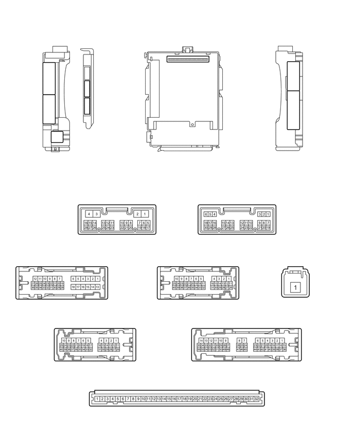
2.229,3.771 2.552,3.979
0.323,0.208
5.833,5.01 6.156,5.219
0.323,0.208
3.906,5.031 4.229,5.24
0.323,0.208
1.125,5.01 1.448,5.219
0.323,0.208
1.781,6.292 2.104,6.5
0.323,0.208
4.927,6.292 5.25,6.5
0.323,0.208
3.417,7.531 3.74,7.74
0.323,0.208
4.688,3.771 5.01,3.979
0.323,0.208
4.031,1.135 4.031,0.854
4.031,0.854 4.146,0.854
false
1.823,2.104 2.073,2.104
false
1.823,1.75 2.073,1.75
false
1.615,3.083 1.615,1.427
1.615,1.427 1.719,1.427
false
1.615,1.75 1.708,1.75
false
1.615,2.104 1.719,2.104
false
1.771,0.979 1.771,0.688
1.771,0.688 1.865,0.688
false
3.479,7.542 3.958,7.875
0.479,0.333
10
false
MB
5.917,5.021 6.365,5.333
0.448,0.313
10
false
3F
1.198,5.021 1.625,5.313
0.427,0.292
10
false
3C
1.865,6.302 2.24,6.615
0.375,0.313
10
false
3B
5.01,6.302 5.406,6.563
0.396,0.26
10
false
3A
3.979,5.042 4.385,5.302
0.406,0.26
10
false
3D
4.75,3.792 5.125,4.031
0.375,0.24
10
false
I13
2.302,3.781 2.604,3.969
0.302,0.188
10
false
I12
5.865,2.167 6.26,2.479
0.396,0.313
10
false
3A
2.125,2.042 2.656,2.417
0.531,0.375
10
false
I12
2.125,1.677 2.594,2.021
0.469,0.344
10
false
I13
0.906,2.125 1.24,2.333
0.333,0.208
10
false
3D
1.083,2.698 1.385,2.896
0.302,0.198
10
false
3F
0.906,1.49 1.323,1.813
0.417,0.323
10
false
3C
5.865,1.469 6.479,1.813
0.615,0.344
10
false
3B
4.198,0.781 4.646,1.01
0.448,0.229
10
false
MB
0.229,0.219 0.74,0.583
0.51,0.365
10
false
*A
1.906,0.625 2.344,0.865
0.438,0.24
10
false
*1
1.542,3.094 2.063,3.521
0.521,0.427
10
false
*3
| *A | Main body ECU (multiplex network body ECU) with 3 connectors | - | - |
| *1 | Main body ECU (multiplex network body ECU) | *2 | 3 connectors |
b.
Measure the resistance and voltage according to the value(s) in the table below.
- HINT:
-
Measure the values on the wire harness side with the connector disconnected.
| Tester Connection | Wiring Color | Terminal Description | Condition | Specified Condition |
|---|---|---|---|---|
| MB-30 (BECU) - Body ground | - | Auxiliary battery power supply | Power switch off | 11 to 14 V |
| MB-31 (ALTB) - Body ground | - | Auxiliary battery power supply | Power switch off | 11 to 14 V |
| MB-32 (IG) - Body ground | - | Power supply (IG signal) | Power switch on (IG) → off | 11 to 14 V → Below 1 V |
| MB-29 (ACC) - Body ground | - | Power supply (ACC signal) | Power switch on (ACC) → off | 11 to 14 V → Below 1 V |
| MB-11 (GND1) - Body ground | - | Ground | Always | Below 1 Ω |
| I12-3 (GND2) - Body ground | W-B - Body ground | Ground | Always | Below 1 Ω |
| MB-2 (FLCY) - Body ground | - | Front door courtesy light switch LH input | Front door LH closed (OFF) → open (ON) | 10 kΩ or higher → Below 1 Ω |
| I13-19 (FRCY) - Body ground | Y - Body ground | Front door courtesy light switch RH input | Front door RH closed (OFF) → open (ON) | 10 kΩ or higher → Below 1 Ω |
| I13-1 (LCTY) - Body ground | LG - Body ground | Rear door courtesy light switch LH input | Rear door LH closed (OFF) → open (ON) | 10 kΩ or higher → Below 1 Ω |
| I13-6 (RCTY) - Body ground | B - Body ground | Rear door courtesy light switch RH input | Rear door RH closed (OFF) → open (ON) | 10 kΩ or higher → Below 1 Ω |
| MB-4 (LGCY) - Body ground | - | Luggage compartment door courtesy light switch input | Luggage compartment door closed (OFF) → open (ON) | 10 kΩ or higher → Below 1 Ω |
| MB-20 (HCTY) - Body ground | - | Engine hood courtesy switch input | Engine hood open (OFF) → closed (ON) | 10 kΩ or higher → Below 1 Ω |
*: w/o Smart Entry and Start System
If the result is not as specified, there may be a malfunction in the wire harness.
c.
Reconnect the main body ECU (multiplex network body ECU) connectors.
d.
Measure the voltage and resistance according to the value(s) in the table below.
| Tester Connection | Wiring Color | Terminal Description | Condition | Specified Condition |
|---|---|---|---|---|
| I13-7 (LSFL) - Body ground | V - Body ground | Front door LH unlock detection switch input | Front door LH unlocked | Below 1 V |
| I13-7 (LSFL) - Body ground | V - Body ground | Front door LH unlock detection switch input | Front door LH locked | Pulse generation |
| I13-18 (LSFR) - Body ground | W - Body ground | Front door RH unlock detection switch input | Front door RH unlocked | Below 1 V |
| I13-18 (LSFR) - Body ground | W - Body ground | Front door RH unlock detection switch input | Front door RH locked | Pulse generation |
| 3C-17 (LSR) - Body ground | LG - Body ground | Rear door LH unlock detection switch input | Rear door LH or RH unlocked | Below 1 V |
| 3C-17 (LSR) - Body ground | LG - Body ground | Rear door LH unlock detection switch input | Rear door LH and RH locked | Pulse generation |
| 3A-53 (LSR) - Body ground | Y - Body ground | Rear door RH unlock detection switch input | Rear door RH or LH unlocked | Below 1 V |
| 3A-53 (LSR) - Body ground | Y - Body ground | Rear door RH unlock detection switch input | Rear door RH and LH locked | Pulse generation |
| 3D-14 (SH) - Body ground | R - Body ground | Security horn drive | Security horn sounding
(Theft deterrent system is in alarm sounding state) |
Pulse generation
(Below 1 V ← → 11 to 14 V) |
| 3D-15 (HORN) - Body ground | SB - Body ground | Vehicle horn drive | Vehicle horns sounding
(Theft deterrent system is in alarm sounding state) |
Pulse generation
(Below 1 V ← → 11 to 14 V) |
If the result is not as specified, the main body ECU (multiplex network body ECU) may have a malfunction.