RM2040EQ
_58
Vehicle Interior
_014730
HEATING / AIR CONDITIONING
_0075108
AIR CONDITIONING SYSTEM
U
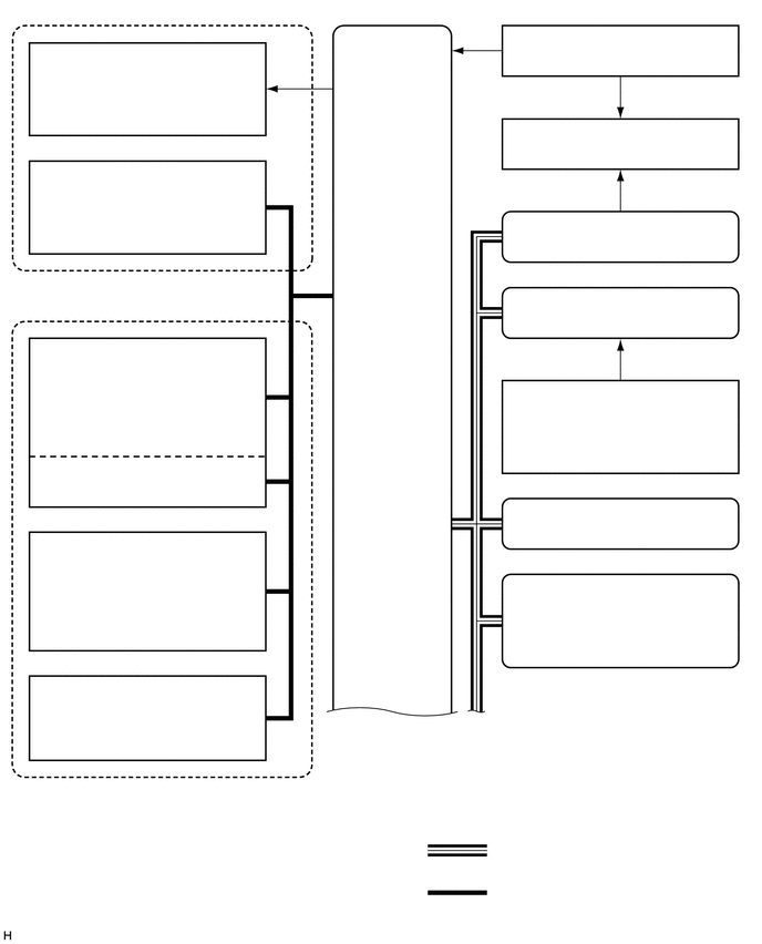
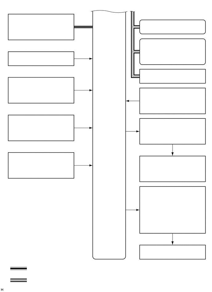
HEATING / AIR CONDITIONING AIR CONDITIONING SYSTEM SYSTEM DIAGRAM
0.688,0.417 2.094,0.75
1.406,0.333
10
false
Blower Motor with Fan Sub-assembly
0.521,1.521 2.271,1.854
1.75,0.333
10
false
No. 1 Blower Damper Servo Sub-assembly (Air Inlet)
3.198,2.677 4.198,3.177
1,0.5
10
false
Air Conditioning Amplifier Assembly
0.427,3.198 2.365,3.531
1.938,0.333
10
false
No. 1 Air Conditioning Radiator Damper Servo Sub-assembly
0.427,3.896 1.208,4.063
0.781,0.167
10
false
- (Air Outlet)
0.427,5.021 2.365,5.354
1.938,0.333
10
false
No. 2 Air Conditioning Radiator Damper Servo Sub-assembly
0.385,6.375 2.323,6.771
1.938,0.396
10
false
Evaporator Temperature Sensor (No. 1 Cooler Thermistor)
0.427,5.719 1.208,5.885
0.781,0.167
10
false
- (Air Mix*1)
0.427,4.302 1.208,4.469
0.781,0.167
10
false
- (Air Mix*2)
0.99,2.552 2.083,2.719
1.094,0.167
10
false
Blower Assembly
0.427,7.323 2.635,7.49
2.208,0.167
10
false
Air Conditioning Radiator Assembly
4.625,7.896 6.323,8.063
1.698,0.167
10
false
: CAN Communication Line
4.625,8.281 6.896,8.448
2.271,0.167
10
false
: Air Conditioning Harness Assembly
4.021,7.542 5.792,7.708
1.771,0.167
10
false
*2: for Front Passenger Side
4.021,7.188 5.146,7.354
1.125,0.167
10
false
*1: for Driver Side
4.813,0.25 6.875,0.417
2.063,0.167
10
false
Inverter with Converter Assembly
4.792,1.125 6.885,1.292
2.094,0.167
10
false
Compressor with Motor Assembly
4.802,2 6.885,2.167
2.083,0.167
10
false
Power Management Control ECU
5.688,2.719 6.021,2.885
0.333,0.167
10
false
ECM
4.927,4.698 6.76,4.865
1.833,0.167
10
false
Combination Meter Assembly
4.948,3.594 6.74,3.927
1.792,0.333
10
false
Engine Coolant Temperature Sensor
5.021,5.417 6.667,5.75
1.646,0.333
10
false
Main Body ECU (Multiplex Network Body ECU)
0.458,0.49 2.333,0.823
1.875,0.333
10
false
Air Conditioning Panel (Heater Control Switch Board)
3.198,2.677 4.198,3.177
1,0.5
10
false
Air Conditioning Amplifier Assembly
0.479,2.635 2.302,2.969
1.823,0.333
10
false
Ambient Temperature Sensor (Thermister Assembly)
0.479,3.906 2.125,4.344
1.646,0.438
10
false
Room Temperature Sensor (Cooler Thermister)
0.646,5.177 2.198,5.583
1.552,0.406
10
false
ECO Mode Switch (ECO Switch Assembly)
0.354,1.76 2.427,1.927
2.073,0.167
10
false
Air Conditioning Pressure Sensor
0.948,8.99 2.646,9.156
1.698,0.167
10
false
: CAN Communication Line
0.948,9.375 3.219,9.542
2.271,0.167
10
false
: Air Conditioning Harness Assembly
0.344,8.635 2.25,8.802
1.906,0.167
10
false
*2: for Radio and Display Type
0.344,8.292 2.365,8.458
2.021,0.167
10
false
*1: for Navigation Receiver Type
4.823,0.688 6.854,0.854
2.031,0.167
10
false
Navigation Receiver Assembly*1
5.656,2.354 6.031,2.521
0.375,0.167
10
false
DLC3
4.938,4.031 6.729,4.365
1.792,0.333
10
false
Engine Room Junction Block Assembly
4.844,6.333 6.844,6.667
2,0.333
10
false
No. 2 Engine Room Relay Block Assembly
4.844,7.031 6.344,7.198
1.5,0.167
10
false
- PTC HTR NO. 1 Relay
4.844,7.469 6.344,7.635
1.5,0.167
10
false
- PTC HTR NO. 2 Relay
5.219,5.302 6.469,5.469
1.25,0.167
10
false
Back Window Glass
5.219,5.719 6.188,5.885
0.969,0.167
10
false
- Deffoger Wire
5.104,8.313 6.573,8.479
1.469,0.167
10
false
Quick Heater Assembly
4.906,3 6.771,3.333
1.865,0.333
10
false
Solar Sensor (Automatic Light Control Sensor)
4.979,1.323 6.708,1.656
1.729,0.333
10
false
Radio and Display Receiver Assembly*2
| Sender | Receiver | Signal | Communication Line |
|---|---|---|---|
| Air conditioning amplifier assembly | Power management control ECU | Heater Idle up request signal | CAN |
| ECO mode switch (eco switch assembly) information | |||
| Engine ON request signal | |||
| Charging control inhibit signal | |||
| Prior A/C control request signal | |||
| Heating performance assistance request signal to transmission system | |||
| Inlet state signal (for cooling battery) | |||
| Stand by for inverter request signal | |||
| Humidity control for compressor with motor assembly start signal | |||
| Compressor with motor assembly start signal | |||
| Compressor with motor assembly Target revolutions signal | |||
| Front blower level indicator signal | |||
| In-vehicle temperature signal | |||
| Ambient temperature display signal | |||
| A/C control state signal | |||
| Air conditioning amplifier assembly | Navigation receiver assembly*1
Radio and display receiver assembly*2 |
AUTO indicator signal | CAN |
| DEF indicator signal | |||
| A/C indicator signal | |||
| Blower level indicator signal | |||
| Outlet indicator signal | |||
| A/C on-screen request signal | |||
| Driver temperature display signal | |||
| Front passenger temperature display signal | |||
| Blower step select information | |||
| Control information status | |||
| Ambient temperature display signal | |||
| A/C control state signal | |||
| Air conditioning amplifier assembly | Combination meter assembly | Ambient temperature display signal | CAN |
| Air conditioning amplifier assembly | Main body ECU (multiplex network body ECU) | Ambient temperature display signal | CAN |
| A/C control state signal | |||
| ECM | Air conditioning amplifier assembly | Engine rpm data | CAN |
| Compulsory internal air circulation command signal at high water temperature | |||
| Engine coolant temperature signal | |||
| Main body ECU (multiplex network body ECU) | Air conditioning amplifier assembly | Trip count | CAN |
| Time count | |||
| Auto dimmer signal | |||
| Destination symbol | |||
| Destination package1 | |||
| Destination package2 | |||
| Steering wheel | |||
| Body type information signal | |||
| Engine starter condition | |||
| Defogger on request | |||
| A/C on request | |||
| Combination meter assembly | Air conditioning amplifier assembly | Vehicle speed signal (meter to other) | CAN |
| Air conditioning panel (heater control switch board) | Air conditioning amplifier assembly | AUTO switch operation signal | LIN |
| OFF switch operation signal | |||
| Blower switch operation signal (up, down) | |||
| MODE switch operation signal | |||
| DEF switch operation signal | |||
| RDEF switch operation signal | |||
| DUAL switch operation signal | |||
| REC/FRS switch operation signal | |||
| A/C switch operation signal | |||
| Driver side set temperature switch operation signal | |||
| Front passenger set temperature switch operation signal | |||
| Air conditioning amplifier assembly | Air conditioning panel (heater control switch board) | Entire front panel display instruction signal | LIN |
| Auto display instruction signal | |||
| Blower level display instruction signal | |||
| A/C display instruction signal | |||
| Rec display instruction signal | |||
| Driver air outlet display instruction signal | |||
| RDEF display instruction signal | |||
| DUAL display instruction signal | |||
| Entire front panel display instruction signal | |||
| Driver set temperature display instruction signal | |||
| Front passenger set temperature display instruction signal | |||
| Dimmer signal |
*1: for Navigation Receiver Type
*2: for Radio and Display Type