AUDIO / VIDEO AUDIO AND VISUAL SYSTEM B1579 Voice Recognition Microphone Disconnected
DESCRIPTION
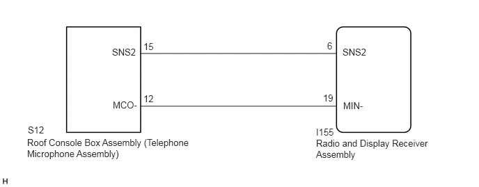
The radio and display receiver assembly and roof console box assembly (telephone microphone assembly) are connected to each other using the microphone connection detection signal lines.
This DTC is stored when a microphone connection detection signal line is disconnected.
| DTC No. | Detection Item | DTC Detection Condition | Trouble Area |
|---|---|---|---|
| B1579 | Voice Recognition Microphone Disconnected | Microphone signal is lost | ·
Roof console box assembly ·
Telephone microphone assembly ·
Radio and display receiver assembly ·
Harness or connector |
WIRING DIAGRAM
PROCEDURE
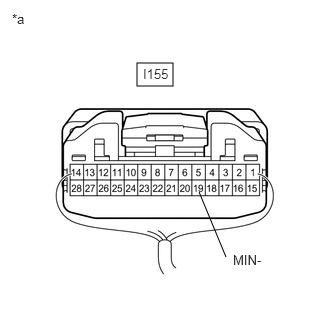
| *a | Component with harness connected
(Radio and Display Receiver Assembly) |
Measure the resistance according to the value(s) in the table below.
- Standard Resistance:
Tester Connection Condition Specified Condition I155-19 (MIN-) - Body ground Always Below 1 Ω
- Result:
Proceed to OK NG
OK
NG
Disconnect the I155 radio and display receiver assembly connector.
Disconnect the S12 roof console box assembly (telephone microphone assembly) connector.
Measure the resistance according to the value(s) in the table below.
- Standard Resistance:
Tester Connection Condition Specified Condition I155-6 (SNS2) - S12-15 (SNS2) Always Below 1 Ω I155-19 (MIN-) - S12-12 (MCO-) Always Below 1 Ω I155-6 (SNS2) - Body ground Always 10 kΩ or higher I155-19 (MIN-) - Body ground Always 10 kΩ or higher
- Result:
Proceed to OK NG
OK
NG
Remove the roof console box assembly (telephone microphone assembly).
Click hereVehicle Interior>LIGHTING (INT)>PERSONAL LIGHT>REMOVAL
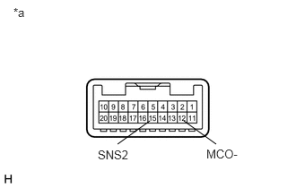
| *a | Component without harness connected
(Roof Console Box Assembly (Telephone Microphone Assembly)) |
Measure the resistance according to the value(s) in the table below.
- Standard Resistance:
Tester Connection Condition Specified Condition 15 (SNS2) - 12 (MCO-) Always Below 1 Ω
- Result:
Proceed to OK NG
OK
NG
Replace the telephone microphone assembly with a new or known good one.
Click hereAudio / Visual / Telematics>AUDIO / VIDEO>MICROPHONE>REMOVAL
Clear the DTCs.
Click hereAudio / Visual / Telematics>AUDIO / VIDEO>AUDIO AND VISUAL SYSTEM>DTC CHECK / CLEAR
- Body Electrical > Navigation System > Clear DTCs
- 50002 212
Recheck for DTCs and check that no DTCs are output.
- Body Electrical > Navigation System > Trouble Codes
- 50001 212
- OK:
No DTCs are output.
- Result:
Proceed to OK NG
OK
NG