 |
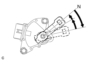
Turn the lever clockwise until it stops, then turn it counterclockwise 2 notches.
SHIFT LEVER POSITION SENSOR > INSTALLATION |
| 1. INSTALL SHIFT LEVER POSITION SENSOR |
Install the shift lever position sensor to the manual valve shaft.
Temporarily install the 2 bolts.
Install a new lock plate and tighten the nut.
Temporarily install the control shaft lever to the manual valve shaft.
|
Turn the lever clockwise until it stops, then turn it counterclockwise 2 notches.
Remove the control shaft lever from the manual valve shaft.
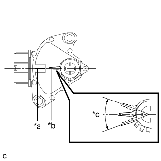 |
Align the protruding part with the neutral basic line.
| *a | Neutral Basic Line |
| *b | Protruding |
| *c | Range of Play |
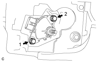 |
Tighten the 2 bolts in the order shown in the illustration.
Using a screwdriver, secure the nut with the lock plate.
Install the control shaft lever, washer, and nut to the manual valve shaft.
Connect the connector to the shift lever position sensor.
| 2. CONNECT TRANSMISSION CONTROL CABLE ASSEMBLY |
Move the shift lever to the N position.
Install a new clip to the control bracket.
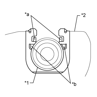 |
Install the transmission control cable assembly to the control bracket.
| *1 | Transmission Control Cable Assembly |
| *2 | No. 1 Transmission Control Cable Bracket |
| *a | Claw A |
| *b | Claw B |
Install the transmission control cable assembly to the control shaft lever with the nut.
| 3. INSPECT SHIFT LEVER POSITION SENSOR POSITION |
Apply the parking brake.
Lock the wheels with chocks to secure the vehicle.
Turn the power switch on (READY).
Move the shift lever to D and release the brake.
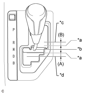 |
Slowly move the shift lever to N and measure moving distance (A) of the shift lever from the original point to the gear disengagement point.
| *a | Gear Disengagement Point |
| *b | N Position |
| *c | R Position |
| *d | D Position |
Move the shift lever to R and release the brake.
Slowly move the shift lever to N and measure moving distance (B) of the shift lever from the original point to the vehicle disengagement point.
Check that moving distances (A) and (B) shown in the illustration are almost the same.
| 4. ADJUST SHIFT LEVER POSITION SENSOR POSITION |
If moving distance (A) is shorter than (B). [*1]
Move the shift lever to N.
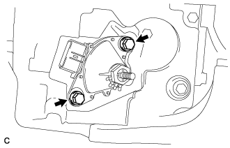 |
Loosen the 2 bolts.
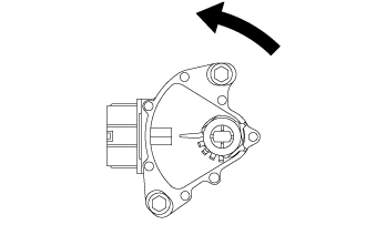 |
Slightly turn the shift lever position sensor counterclockwise.
|
Tighten the 2 bolts in the order shown in the illustration.
Recheck the shift lever position sensor.
If moving distance (B) is shorter than (A). [*2]
Move the shift lever to N.
|
Loosen the 2 bolts.
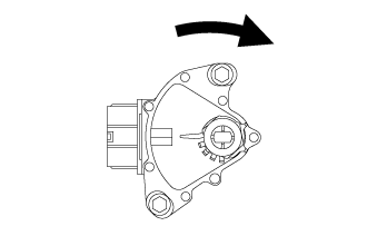 |
Slightly turn the shift lever position sensor clockwise.
|
Tighten the 2 bolts in the order shown in the illustration.
Recheck the shift lever position sensor.
| 5. INSPECT SHIFT LEVER POSITION |
While moving the shift lever from the N position to each position, check that the lever moves smoothly and that the shift position indicator comes on properly according to the shift lever position.
Put the vehicle into the READY-on state and check the following:
When the shift lever is moved to the D position, the vehicle moves forward.
When the shift lever is moved to the R position, the vehicle moves in reverse.
| 6. ADJUST SHIFT LEVER POSITION |
Move the shift lever to N.
Remove the console box (Click here).
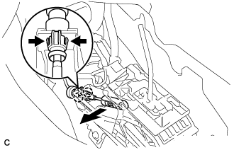 |
Disconnect the end of the transmission control cable assembly from the lower shift lever assembly.
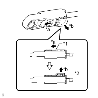 |
Slide the slider of the transmission control cable assembly in the direction indicated by the arrow and pull the lock piece outward.
| *1 | Slider |
| *2 | Lock Piece |
| *a | Slide |
| *b | Pull |
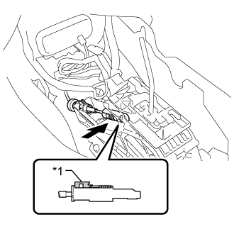 |
Install the end of the transmission control cable assembly to the lower shift lever assembly.
| *1 | Lock Piece |
Push the lock piece into the adjuster case.
After adjusting the shift lever position, check the operation and function of the shift lever. If there is a problem, adjust the position again.
Install the console box (Click here).
| 7. INSTALL ENGINE UNDER COVER LH |
| 8. INSTALL FRONT WHEEL OPENING EXTENSION PAD LH |
| 9. INSTALL ENGINE UNDER COVER RH |
| 10. REMOVE FRONT WHEEL OPENING EXTENSION PAD RH |