 |
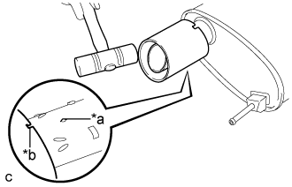
Align the concave area of each baffle with the protruding part of the tail exhaust pipe assembly as shown in the illustration.
| *a | Protruding Part |
| *b | Concave |
EXHAUST PIPE > INSTALLATION |
| 1. INSTALL TAIL EXHAUST PIPE BAFFLE SUB-ASSEMBLY |
Temporarily install a new tail exhaust pipe baffle sub-assembly to the tail exhaust pipe assembly.
|
Align the concave area of each baffle with the protruding part of the tail exhaust pipe assembly as shown in the illustration.
| *a | Protruding Part |
| *b | Concave |
Using a plastic hammer, uniformly tap the tail exhaust pipe baffle sub-assemblies onto the tail exhaust pipe assembly.
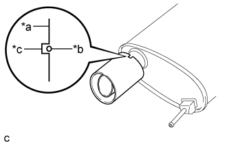 |
Check that the concave area of each baffle is aligned with the protruding part on the bottom of the tail exhaust pipe assembly as shown in the illustration.
| *a | Baffle Edge |
| *b | Protruding Part |
| *c | Concave |
| 2. INSTALL FRONT EXHAUST PIPE ASSEMBLY |
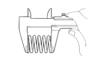 |
Using a vernier caliper, measure the free length of the compression spring.
| Standard | 42.0 mm (1.65 in.) |
| Minimum | 40.5 mm (1.60 in.) |
Fully insert a new gasket to the exhaust manifold converter sub-assembly.
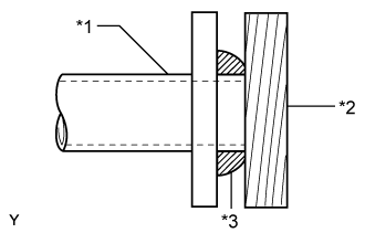 |
Using a plastic hammer and wooden block, tap in the new gasket until its surface is flush with the exhaust manifold converter sub-assembly.
| *1 | Exhaust Manifold Converter Sub-assembly |
| *2 | Wooden Block |
| *3 | Gasket |
Connect the front exhaust pipe assembly to the exhaust pipe support.
Install the front exhaust pipe assembly with the 2 compression springs and 2 bolts.
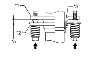 |
| *1 | Exhaust Manifold Converter Sub-assembly |
| *2 | Front Exhaust Pipe Assembly |
| *3 | Gasket |
| *a | Space between flanges: 8.5 mm (0.335 in.) |
| 3. INSTALL CENTER EXHAUST PIPE ASSEMBLY |
Install a new gasket to the front exhaust pipe assembly.
Connect the center exhaust pipe assembly to the exhaust pipe support.
Install the center exhaust pipe assembly with the 2 nuts.
| 4. INSTALL TAIL EXHAUST PIPE ASSEMBLY |
|
Using a vernier caliper, measure the free length of the compression spring.
| Standard | 40.0 mm (1.57 in.) |
| Minimum | 38.5 mm (1.52 in.) |
Fully insert a new gasket to the center exhaust pipe assembly.
|
Using a plastic hammer and wooden block, tap in the new gasket until its surface is flush with the center exhaust pipe assembly.
| *1 | Center Exhaust Pipe Assembly |
| *2 | Wooden Block |
| *3 | Gasket |
Connect the tail exhaust pipe assembly to the 3 exhaust pipe supports.
Install the tail exhaust pipe assembly with the 2 compression springs and 2 bolts.
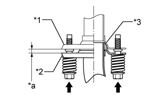 |
| *1 | Tail Exhaust Pipe Assembly |
| *2 | Center Exhaust Pipe Assembly |
| *3 | Gasket |
| *a | Space between flanges: 6.5 mm (0.256 in.) |
| 5. INSTALL HEATED OXYGEN SENSOR |
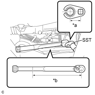 |
Using SST, install the heated oxygen sensor to the front exhaust pipe.
| *a | Fulcrum Length 30 mm |
| *b | Fulcrum Length 300 mm |
Connect the heated oxygen sensor connector.
| 6. INSPECT FOR EXHAUST GAS LEAK |