 |
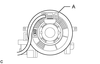
Check if the spiral cable sub-assembly is centered.
 | Colored Part |
- HINT:
- When the spiral cable sub-assembly is centered, the part indicated by A is positioned at the top and the colored part shown in the illustration is visible.
SPIRAL CABLE > INSTALLATION |
| 1. INSPECT SPIRAL CABLE SUB-ASSEMBLY |
|
Check if the spiral cable sub-assembly is centered.
| Colored Part |
If the spiral cable sub-assembly is not centered, center it.
If the cable cannot be centered, it is possible that the spiral cable sub-assembly is broken. Replace the spiral cable with sensor sub-assembly with a new one.
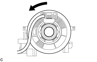 |
While pushing on the interlock indicated in the illustration, rotate the spiral cable sub-assembly counterclockwise slowly by hand until it stops.
 | Interlock |
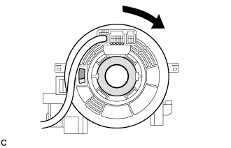 |
Rotate the spiral cable sub-assembly clockwise approximately 2.5 turns to the position where the colored part shown in the illustration is visible.
| Colored Part |
| Interlock |
| 2. INSTALL SPIRAL CABLE SUB-ASSEMBLY |
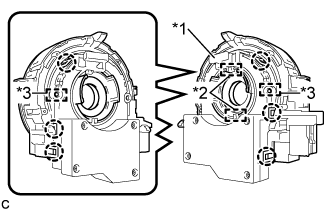 |
Align the 2 pins and 2 guides, and engage the 6 claws to install the spiral cable sub-assembly to the steering sensor.
| *1 | Lock Pin |
| *2 | Guide |
| *3 | Pin |
Remove the lock pin from the steering sensor.
| 3. TURN FRONT WHEELS TO FACE STRAIGHT AHEAD |
| 4. INSTALL SPIRAL CABLE WITH SENSOR SUB-ASSEMBLY |
Check that the power switch is off.
Check that the cable is disconnected from the negative (-) auxiliary battery terminal.
Check that the front wheels are facing straight ahead.
Set the turn signal switch to the neutral position.
Engage the 3 claws to install the spiral cable with sensor sub-assembly.
Connect the each connector.
| 5. INSTALL UPPER STEERING COLUMN COVER |
Engage the 2 claws to install the upper steering column cover.
Engage the 4 clips and 2 guides to the upper steering column cover.
| 6. INSTALL LOWER STEERING COLUMN COVER |
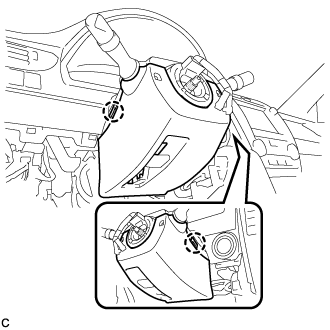 |
Engage the 2 claws to install the lower steering column cover.
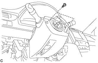 |
Install the 2 screws.
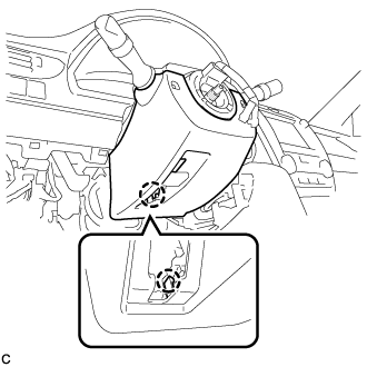 |
Engage the claw.
| 7. INSPECT AND ADJUST SPIRAL CABLE WITH SENSOR SUB-ASSEMBLY |
Check that the power switch is off.
Check that the cable is disconnected from the negative (-) auxiliary battery terminal.
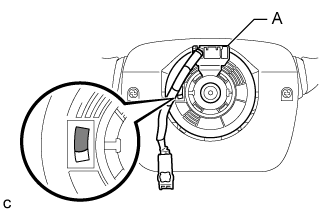 |
Check if the spiral cable with sensor sub-assembly is centered.
| Colored Part |
If the spiral cable with sensor sub-assembly is not centered, center it.
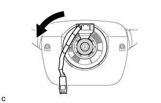 |
While pushing on the interlock indicated in the illustration, rotate the spiral cable with sensor sub-assembly counterclockwise slowly by hand until it stops.
| Interlock |
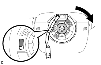 |
Rotate the spiral cable with sensor sub-assembly clockwise approximately 2.5 turns to the position where the colored part shown in the illustration is visible.
| Colored Part |
| Interlock |
| 8. INSTALL STEERING WHEEL ASSEMBLY |