 |
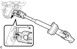
Install the steering intermediate shaft assembly to the steering column assembly.
| *a | Matchmark |
- NOTICE:
- Align the matchmarks on the steering intermediate shaft assembly and the steering column assembly.
STEERING COLUMN ASSEMBLY > INSTALLATION |
| 1. INSTALL STEERING INTERMEDIATE SHAFT ASSEMBLY |
|
Install the steering intermediate shaft assembly to the steering column assembly.
| *a | Matchmark |
Install the bolt.
| 2. INSTALL STEERING POST ASSEMBLY |
Install the steering post assembly with the 4 nuts.
Install the ground wire with the bolt.
Engage the clamp.
Connect the 2 connectors.
Connect the connectors and engage the wire harness clamps to the steering post assembly.
| 3. INSTALL NO. 2 AIR DUCT SUB-ASSEMBLY (for LHD) |
Engage the clamp to install the No. 2 air duct sub-assembly.
Engage the 2 claws and guide.
| 4. INSTALL NO. 2 AIR DUCT SUB-ASSEMBLY (for RHD) |
Engage the 2 claws to install the No. 2 air duct sub-assembly.
Install the bolt.
| 5. CONNECT STEERING INTERMEDIATE SHAFT ASSEMBLY |
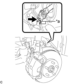 |
Connect the steering intermediate shaft assembly to the steering link assembly.
| *a | Matchmark |
Install the bolt.
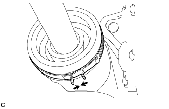 |
Tighten the clamp.
| 6. INSTALL TURN SIGNAL SWITCH ASSEMBLY WITH SPIRAL CABLE SUB-ASSEMBLY |
Engage the 3 claws to install the turn signal switch assembly with spiral cable sub-assembly to the steering post assembly.
Connect the connectors to the turn signal switch assembly with spiral cable sub-assembly.
| 7. INSTALL UPPER STEERING COLUMN COVER |
Engage the 2 claws to install the upper steering column cover.
Engage the 4 clips and 2 guides to the upper steering column cover.
| 8. INSTALL LOWER STEERING COLUMN COVER |
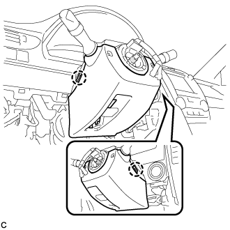 |
Engage the 2 claws to install the lower steering column cover.
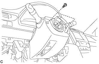 |
Install the 2 screws.
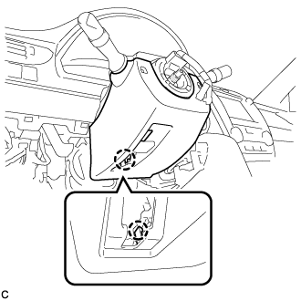 |
Engage the claw.
| 9. INSTALL INSTRUMENT PANEL SUB-ASSEMBLY |
Engage the 5 clips and 3 guides.
Install the instrument panel sub-assembly with the 2 bolts <B>.
| 10. CONNECT HOOD LOCK CONTROL LEVER SUB-ASSEMBLY |
Engage the claw and 2 guides to connect the hood lock control lever sub-assembly.
| 11. INSTALL INSTRUMENT SIDE PANEL |
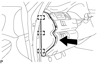 |
Engage the 3 guides.
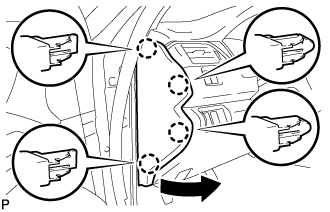 |
Engage the 4 claws to install the instrument side panel LH as shown in the illustration.
| 12. INSTALL FRONT DOOR OPENING TRIM WEATHERSTRIP |
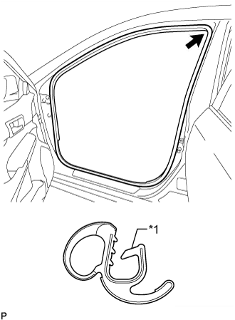 |
Align the alignment mark (Yellow) on the weatherstrip with the protruding portion on the body indicated by the arrow in the illustration, and install the front door opening trim weatherstrip LH.
| *1 | Alignment Mark (Yellow) |
| 13. INSTALL COWL SIDE TRIM SUB-ASSEMBLY |
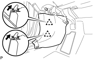 |
Insert the 2 clips in the direction indicated by the arrows shown in the illustration to engage them.
Install the cowl side trim sub-assembly LH with the clip.
| 14. INSTALL FRONT DOOR SCUFF PLATE |
Engage the 10 claws to install the front door scuff plate LH.
| 15. TURN FRONT WHEELS TO FACE STRAIGHT AHEAD |
| 16. INSPECT AND ADJUST SPIRAL CABLE WITH SENSOR SUB-ASSEMBLY |
Check that the power switch is off.
Check that the cable is disconnected from the negative (-) auxiliary battery terminal.
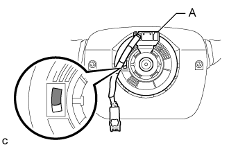 |
Check if the spiral cable with sensor sub-assembly is centered.
 | Colored Part |
If the spiral cable with sensor sub-assembly is not centered, center it.
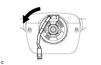 |
While pushing on the interlock indicated in the illustration, rotate the spiral cable with sensor sub-assembly counterclockwise slowly by hand until it stops.
 | Interlock |
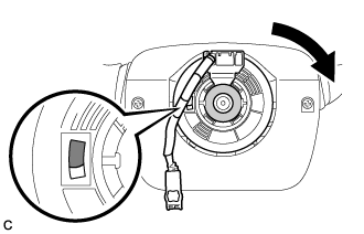 |
Rotate the spiral cable with sensor sub-assembly clockwise approximately 2.5 turns to the position where the colored part shown in the illustration is visible.
| Colored Part |
| Interlock |
| 17. INSTALL STEERING WHEEL ASSEMBLY |
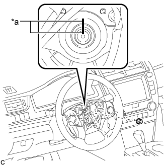 |
Install the steering wheel assembly aligning the matchmarks on the steering wheel assembly and steering main shaft.
| *a | Matchmark |
Install the steering wheel assembly set nut.
Connect the connectors to the spiral cable sub-assembly.
| 18. INSPECT STEERING WHEEL CENTER POINT |
| 19. INSTALL HORN BUTTON ASSEMBLY |
| 20. INSTALL FRONT WHEEL |