METER / GAUGE SYSTEM > SYSTEM DESCRIPTION |
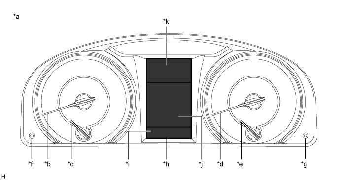
| OUTLINE OF COMBINATION METER ASSEMBLY |
| *a | Indication Example | *b | Hybrid System Indicator |
| *c | Engine Coolant Temperature Receiver Gauge | *d | Speedometer |
| *e | Fuel Receiver Gauge | *f | Light Control Switch Knob |
| *g | ODO/TRIP Switch Knob | *h | Multi-information Display |
| *i | Display Area A | *j | Display Area B |
| *k | Display Area C | - | - |
| INPUT AND OUTPUT SIGNALS OF COMBINATION METER ASSEMBLY |
Meter or Gauge
| Item | Condition | Input/Output | Communication line | Signal | Component |
| Speedometer | Gauge | Input | CAN | Vehicle speed (SP1) signal | Brake booster with master cylinder assembly (Skid control ECU) |
| - | Direct line | Vehicle speed pulse input signal | |||
| Output | CAN | Vehicle speed signal (meter to other) | Related ECUs | ||
| Speed tolerance A signal | |||||
| Speed tolerance B signal | |||||
| Direct line | Vehicle speed pulse output signal | Related ECUs | |||
| Fuel receiver gauge | Gauge | Input | CAN | Shift position P signal | Power management control ECU |
| Shift position N signal | |||||
| Vehicle speed (SP1) signal | Brake booster with master cylinder assembly (Skid control ECU) | ||||
| Parking brake switch signal | Main body ECU (Multiplex network body ECU) | ||||
| Direct line | Fuel level signal | Fuel sender gauge assembly | |||
| - | Output | CAN | Fuel gauge state signal | Radio and display receiver assembly | |
| Fuel gauge indication signal | |||||
| Fuel level in main tank signal | ECM | ||||
| Engine coolant temperature receiver gauge | Gauge | Input | CAN | Engine coolant temperature signal | ECM |
| Hybrid system indicator | Gauge | Input | CAN | Eco-zone indicator level signal | Power management control ECU |
Warning or Indicator
| Item | Condition | Input/Output | Communication line | Signal | Component |
| Master warning light | Comes on/Blinks | Input | CAN/Direct line | Each warning signal | Related ECUs |
| Brake warning light / red (malfunction) | Comes on | Input | CAN | Brake warning light / red (malfunction) control flag signal | Brake booster with master cylinder assembly (Skid control ECU) |
| Parking brake switch signal | Main body ECU (Multiplex network body ECU) | ||||
| Driver seat belt warning light | Comes on/Blinks | Input | CAN | Driver seat belt buckle switch signal | Main body ECU (Multiplex network body ECU) |
| Shift position P signal | ECM | ||||
| Parking brake switch signal | Main body ECU (Multiplex network body ECU) | ||||
| SRS warning light | Comes on | Input | CAN | Airbag warning light control request signal | Airbag sensor assembly |
| Test mode signal | Power management control ECU | ||||
| EPS warning light | Comes on/Blinks | Input | CAN | Demand signal to meter | Power steering ECU assembly |
| MIL (Check engine warning light) | Comes on/Blinks | Input | Direct line | MIL (Check engine warning light) request signal | ECM |
| Slip indicator light | Comes on/Blinks | Input | CAN | Slip indicator signal | Brake booster with master cylinder assembly (Skid control ECU) |
| VSC OFF indicator light | Comes on | Input | CAN | VSC OFF light signal | Brake booster with master cylinder assembly (Skid control ECU) |
| ABS warning light | Comes on/Blinks | Input | CAN | ABS warning light control flag signal | Brake booster with master cylinder assembly (Skid control ECU) |
| Brake warning light / yellow (minor malfunction) | Comes on/Blinks | Input | CAN | Brake warning light / yellow (minor malfunction) control flag signal | Brake booster with master cylinder assembly (Skid control ECU) |
| Fuel level warning light | Comes on | Input | Direct line | Fuel level signal | Fuel sender gauge assembly |
| Rear fog indicator light* | Comes on | Input | CAN | Rear fog light request signal | Main body ECU (Multiplex network body ECU) |
| READY indicator light | Comes on/Blinks | Input | CAN | READY signal | Power management control ECU |
| High beam indicator light | Comes on | Input | CAN | High beam headlight request signal | Main body ECU (Multiplex network body ECU) |
| Front fog indicator light | Comes on | Input | CAN | Front fog light request signal | Main body ECU (Multiplex network body ECU) |
| Tail indicator light | Comes on | Input | CAN | Taillight request signal | Main body ECU (Multiplex network body ECU) |
| Turn indicator light | Blinks | Input | CAN | Flasher request signal | Main body ECU (Multiplex network body ECU) |
| Direct line | LH turn signal switch signal | Headlight dimmer switch assembly | |||
| RH turn signal switch signal | |||||
| Turn signal switch position signal | |||||
| Hazard warning switch signal | Air conditioning control assembly (Hazard warning signal switch) | ||||
| - | Output | CAN | Turn signal switch state signal | Related ECUs | |
| Hazard switch state signal | |||||
| Direct line | LH turn signal switch signal | Each turn signal light | |||
| RH turn signal switch signal | |||||
| Hazard warning switch signal | |||||
| EV indicator light | Comes on | Input | CAN | Engine mode ID signal | Power management control ECU |
| Engine RPM data signal | ECM | ||||
| Vehicle speed (SP1) signal | Brake booster with master cylinder assembly (Skid control ECU) |
Multi-information Display
| Item | Condition | Input/Output | Communication line | Signal | Component | Display Area |
| Opening | Displayed | - | - | - | - | All |
| Odometer | Displayed | Input | CAN | Vehicle speed pulse signal integrated value signal | Brake booster with master cylinder assembly (Skid control ECU) | A |
| Vehicle speed (SP1) signal | ||||||
| - | ODO/TRIP change switch signal | ODO/TRIP switch knob (Combination meter assembly) | ||||
| - | Output | CAN | Odometer unit signal | Related ECUs | ||
| Odometer signal | ||||||
| TRIP A/TRIP B meter | Displayed | Input | CAN | Vehicle speed pulse signal integrated value signal | Brake booster with master cylinder assembly (Skid control ECU) | A |
| Vehicle speed (SP1) signal | ||||||
| - | ODO/TRIP change switch signal | ODO/TRIP switch knob (Combination meter assembly) | ||||
| Current fuel consumption | Displayed | Input | CAN | Vehicle speed (SP1) signal | Brake booster with master cylinder assembly (Skid control ECU) | B |
| Vehicle speed pulse signal integrated value signal | ||||||
| Fuel consumption signal | ECM | |||||
| READY signal | Power management control ECU | |||||
| - | Output | CAN | Drive monitor unit signal 0 | Radio and display receiver assembly | ||
| Drive monitor display signal (Current fuel consumption) | ||||||
| Average fuel consumption (After reset) | Displayed | Input | CAN | Vehicle speed (SP1) signal | Brake booster with master cylinder assembly (Skid control ECU) | B |
| Vehicle speed pulse signal integrated value signal | ||||||
| Engine RPM data signal | ECM | |||||
| Total average fuel consumption reset request signal | Radio and display receiver assembly | |||||
| READY signal | Power management control ECU | |||||
| Direct line | Reset signal | Steering pad switch assembly | ||||
| - | Output | CAN | Drive monitor unit signal 6 | Radio and display receiver assembly | ||
| Drive monitor display signal (Total average fuel consumption) | ||||||
| Average fuel consumption (After start) | Displayed | Input | CAN | Fuel consumption signal | ECM | B |
| Vehicle speed (SP1) signal | Brake booster with master cylinder assembly (Skid control ECU) | |||||
| Vehicle speed pulse signal integrated value signal | ||||||
| READY signal | Power management control ECU | |||||
| Average speed (After reset) | Displayed | Input | CAN | Vehicle speed (SP1) signal | Brake booster with master cylinder assembly (Skid control ECU) | B |
| Vehicle speed pulse signal integrated value signal | ||||||
| READY signal | Power management control ECU | |||||
| Direct line | Reset signal | Steering pad switch assembly | ||||
| Average speed (After start) | Displayed | Input | CAN | Vehicle speed (SP1) signal | Brake booster with master cylinder assembly (Skid control ECU) | B |
| Vehicle speed pulse signal integrated value signal | ||||||
| READY signal | Power management control ECU | |||||
| - | Output | CAN | Drive monitor unit signal 1 | Radio and display receiver assembly | ||
| Drive monitor display signal (After starting average speed) | ||||||
| Elapsed time (After reset) | Displayed | Input | CAN | READY signal | Power management control ECU | B |
| Direct line | Reset signal | Steering pad switch assembly | ||||
| Elapsed time (After start) | Displayed | Input | CAN | READY signal | Power management control ECU | B |
| - | Output | CAN | Drive monitor display signal (After starting driving time) | Radio and display receiver assembly | ||
| Drivable distance | Displayed | Input | CAN | Fuel consumption signal | ECM | B |
| Vehicle speed pulse signal integrated value signal | Brake booster with master cylinder assembly (Skid control ECU) | |||||
| READY signal | Power management control ECU | |||||
| Direct line | Fuel level signal | Fuel sender gauge assembly | ||||
| - | Output | CAN | Drive monitor unit signal 4 | Radio and display receiver assembly | ||
| Drive monitor display signal (Drivable distance) | ||||||
| Driving distance (After reset) | Displayed | Input | CAN | READY signal | Power management control ECU | B |
| Vehicle speed (SP1) signal | Brake booster with master cylinder assembly (Skid control ECU) | |||||
| Vehicle speed pulse signal integrated value signal | ||||||
| Driving distance (After start) | Displayed | Input | CAN | READY signal | Power management control ECU | B |
| Vehicle speed (SP1) signal | Brake booster with master cylinder assembly (Skid control ECU) | |||||
| Vehicle speed pulse signal integrated value signal | ||||||
| Energy flow | Displayed | Input | CAN | Energy flow (Engine → Wheels) signal | Power management control ECU | B |
| Energy flow (Engine → Motor) signal | ||||||
| Energy flow (Motor → Wheels) signal | ||||||
| Energy flow (Motor → HV battery) signal | ||||||
| State of charge signal | ||||||
| Vehicle speed (SP1) signal | Brake booster with master cylinder assembly (Skid control ECU) | |||||
| Other (Blank) | Displayed | - | - | - | - | B |
| Drive information tab | Displayed | - | - | - | - | B |
| Cruise control tab | Displayed | - | - | - | Power management control ECU | B |
| Message tab | Displayed | - | - | - | - | B |
| Setting tab | Displayed | - | - | - | - | B |
| Shift position | Displayed | Input | CAN | Shift position P signal | Power management control ECU | C |
| Shift position R signal | ||||||
| Shift position N signal | ||||||
| Shift position D signal | ||||||
| Shift position B signal | ||||||
| Cruise control SET indicator light | Displayed | Input | CAN | Cruise set indicator signal | Power management control ECU | C |
| Cruise control indicator light | Displayed | Input | CAN | Cruise main indicator signal | Power management control ECU | C |
| Cruise control warning signal | ||||||
| ECO MODE indicator light | Displayed | Input | CAN | ECO MODE indicator signal | Power management control ECU | C |
| EV MODE indicator light | Displayed | Input | CAN | EV MODE message signal | Power management control ECU | C |
| Outside temperature | Displayed | Input | CAN | Ambient temperature display signal | Air conditioning amplifier assembly | C |
| 0 or 0.5°C below decimal point of ambient temperature display switch signal | ||||||
| Icy street warning light | Displayed | Input | CAN | Ambient temperature display signal | Air conditioning amplifier assembly | C |
| 0 or 0.5°C below decimal point of ambient temperature display switch signal | ||||||
| Phone (Received call) | Displayed | Input | CAN/Local bus | Phone (Received call) signal | Radio and display receiver assembly | B |
| Maintenance Mode | Displayed | Input | CAN | Check mode 1 signal | Power management control ECU | B |
| Certification Mode | Displayed | Input | CAN | Check mode 2 signal | Power management control ECU | B |
| Shift to P position when parked | Displayed | Input | CAN | NDB warning signal | Power management control ECU | B |
| Each door open | Displayed | Input | CAN | Driver door open display signal | Certification ECU (Smart Key ECU Assembly) | B |
| Front passenger door open display signal | ||||||
| Rear right door open display signal | ||||||
| Rear left door open display signal | ||||||
| Driver door courtesy switch signal | Main body ECU (Multiplex network body ECU) | |||||
| Front passenger door courtesy switch signal | ||||||
| Rear right door courtesy switch signal | ||||||
| Rear left door courtesy switch signal | ||||||
| Luggage courtesy switch signal | ||||||
| Hood courtesy switch signal | ||||||
| Vehicle speed (SP1) signal | Brake booster with master cylinder assembly (Skid control ECU) | |||||
| Clearance sonar detection (image display) | Displayed | Input | CAN | Cluster indicator turn ON request signal | Clearance warning ECU assembly | B |
| Front center area information signal | ||||||
| Front left area information signal | ||||||
| Rear center area information signal | ||||||
| Rear left area information signal | ||||||
| Rear right area information signal | ||||||
| Sensor diag request signal | ||||||
| Check Park Sonar System | Displayed | Input | CAN | Cluster indicator turn ON request signal | Clearance warning ECU assembly | B |
| Sensor diag request signal | ||||||
| Clean Park Sonar | Displayed | Input | CAN | Cluster indicator turn ON request signal | Clearance warning ECU assembly | B |
| Sensor diag request signal | ||||||
| Auto Power OFF to Conserve Battery | Displayed | Input | CAN | Message request for push start signal | Power management control ECU | B |
| Shift to P position when parked | Displayed | Input | CAN | Smart system warning 2 signal | Certification ECU (Smart key ECU assembly) | B |
| Message request for push start signal | Power management control ECU | |||||
| N position | Displayed | Input | CAN | Accelerator depressed in N position signal | Power management control ECU | B |
| Traction battery preservation mode Restart after shifting to P position | Displayed | Input | CAN | HV battery low voltage warning signal | Power management control ECU | B |
| Check Hybrid System Stop the vehicle in a safe place immediately | Displayed | Input | CAN | HV system malfunction notification signal | Power management control ECU | B |
| Traction battery Low Charges when not in N position | Displayed | Input | CAN | HV battery charge request warning signal | Power management control ECU | B |
| Release Parking Brake | Displayed | Input | CAN | Parking brake switch signal | Main body ECU (Multiplex network body ECU) | B |
| Vehicle speed (SP1) signal | Brake booster with master cylinder assembly (Skid control ECU) | |||||
| Key not detected | Displayed | Input | CAN | Smart system warning 1 signal | Certification ECU (Smart key ECU assembly) | B |
| Charging System Malfunction See Owner's Manual | Displayed | Input | CAN | Charge warning signal | Power management control ECU | B |
| Check Entry & Start System | Displayed | Input | CAN | Smart system warning 1 signal | Certification ECU (Smart key ECU assembly) | B |
| Check Cruise Control System | Displayed | Input | CAN | Cruise control warning signal | Power management control ECU | B |
| Engine Oil Pressure Low | Displayed | Input | CAN | READY signal | Power management control ECU | B |
| Oil pressure lamp lighting prohibition signal | ||||||
| Direct line | Engine oil pressure signal | Engine oil pressure switch assembly | ||||
| Turn Power OFF | Displayed | Input | CAN | Smart system warning 2 signal | Certification ECU (Smart key ECU assembly) | B |
| Message request for push start signal | Power management control ECU | |||||
| Key detected in vehicle | Displayed | Input | CAN | Smart system warning 3 signal | Certification ECU (Smart key ECU assembly) | B |
| Moon Roof opened* | Displayed | Input | CAN | Sliding roof open warning request signal | Main body ECU (Multiplex network body ECU) | B |
| Depress brake pedal, touch POWER switch with key | Displayed | Input | CAN | Smart system warning 1 signal | Certification ECU (Smart key ECU assembly) | B |
| Depress brake pedal and push POWER switch to start | Displayed | Input | CAN | Smart system warning 3 signal | Certification ECU (Smart key ECU assembly) | B |
| Message request for push start signal | Power management control ECU | |||||
| Steering Lock active | Displayed | Input | CAN | Smart system warning 1 signal | Certification ECU (Smart key ECU assembly) | B |
| Message request for push start signal | Power management control ECU | |||||
| Shift to P position to start | Displayed | Input | CAN | P position requirement signal | Power management control ECU | B |
| Key Battery Low | Displayed | Input | CAN | Smart system warning 1 signal | Certification ECU (Smart key ECU assembly) | B |
| Check Headlight System | Displayed | Input | Direct line | Headlight leveling warning signal | Headlight leveling ECU assembly | B |
| Hybrid System Overheat Output Power is limited | Displayed | Input | CAN | Motor inverter high temperature warning signal | Power management control ECU | B |
| Driving force Limited | Displayed | Input | CAN | Under protection T/M control signal | Power management control ECU | B |
| Maintenance Required for Hybrid Battery Cooling Parts at Your Dealer | Displayed | Input | CAN | HV battery cooling system maintenance signal | Power management control ECU | B |
| Low 12-Volt Battery See Owner's Manual | Displayed | Input | CAN | Auxiliary battery low voltage flag signal | Power management control ECU | B |
| Washer Fluid Low | Displayed | Input | Direct line | Washer fluid level signal | Level warning switch assembly | B |
| Fuel Low | Displayed | Input | Direct line | Fuel level signal | Fuel sender gauge assembly | B |
| TRC OFF | Displayed | Input | CAN | Traction off indicator light signal | Brake booster with master cylinder assembly (Skid control ECU) | B |
| Power ON | Displayed | Input | CAN | Smart system warning 1 signal | Certification ECU (Smart key ECU assembly) | B |
| Depress brake pedal and push POWER switch to start | Displayed | Input | CAN | Smart system warning 1 signal | Certification ECU (Smart key ECU assembly) | B |
| EV mode currently not available | Displayed | Input | CAN | EV mode message signal | Power management control ECU | B |
| EV mode not available Warming up | Displayed | Input | CAN | EV mode message signal | Power management control ECU | B |
| EV mode currently not available Low battery | Displayed | Input | CAN | EV mode message signal | Power management control ECU | B |
| EV mode currently not available Excessive speed | Displayed | Input | CAN | EV mode message signal | Power management control ECU | B |
| EV mode currently not available Excessive acceleration | Displayed | Input | CAN | EV mode message signal | Power management control ECU | B |
| EV mode deactivated | Displayed | Input | CAN | EV mode message signal | Power management control ECU | B |
| EV mode deactivated Low battery | Displayed | Input | CAN | EV mode message signal | Power management control ECU | B |
| EV mode deactivated Excessive speed | Displayed | Input | CAN | EV mode message signal | Power management control ECU | B |
| EV mode deactivated Excessive acceleration | Displayed | Input | CAN | EV mode message signal | Power management control ECU | B |
Buzzer
| Item | Condition | Input/Output | Communication line | Signal | Component |
| READY buzzer | Sounds once | Input | CAN | READY buzzer signal | Power management control ECU |
| Seat belt warning buzzer | Sounds intermittently | Input | CAN | Driver seat buckle switch signal | Main body ECU (Multiplex network body ECU) |
| Shift position R signal | Power management control ECU | ||||
| Brake control system power low warning buzzer | Sounds intermittently | Input | CAN | Buzzer control flag signal | Brake booster with master cylinder assembly (Skid control ECU) |
| EPS warning buzzer | Sounds once | Input | CAN | Demand buzzer to meter signal | Power steering ECU assembly |
| Smart key warning buzzer | Sounds intermittently | Input | CAN | Meter buzzer intermittence request signal | Certification ECU (Smart key ECU assembly) |
| Sounds intermittently (Maximum 9 times) | Input | CAN | Meter buzzer intermittence request (0.7 sec. cycle) signal | Certification ECU (Smart key ECU assembly) | |
| Sounds continuously | Input | CAN | Meter buzzer continuation request signal | Certification ECU (Smart key ECU assembly) | |
| Sounds once | Input | CAN | Meter buzzer single-shot request signal | Certification ECU (Smart key ECU assembly) | |
| Brake system temperature rise or active test buzzer | Sounds intermittently | Input | CAN | Buzzer control flag signal | Brake booster with master cylinder assembly (Skid control ECU) |
| Multi-information display warning buzzer | Sounds once | Input | CAN | Multi-information display warning signal | Related ECUs |
| Direct line | |||||
| Accelerator pedal depressed with shift position N buzzer | Sounds continuously | Input | CAN | Accelerator depressed in N position signal | Power management control ECU |
| Hybrid control system warning buzzer | Sounds once | Input | CAN | HV system malfunction notification signal | Power management control ECU |
| Sounds intermittently | |||||
| Hybrid battery low voltage buzzer | Sounds intermittently | Input | CAN | HV battery charge request warning signal | Power management control ECU |
| Sounds continuously | Input | CAN | HV battery low voltage warning signal | ||
| Immobiliser key identification completion buzzer | Sounds once | Input | CAN | Immobiliser key identification completion signal | Certification ECU (Smart key ECU assembly) |
| Shift position P request buzzer | Sounds continuously | Input | CAN | NDB warning signal | Power management control ECU |
| Driving with parking brake unreleased warning buzzer | Sounds intermittently | Input | CAN | Parking brake switch signal | Main body ECU (Multiplex network body ECU) |
| Vehicle speed (SP1) signal | Brake booster with master cylinder assembly (Skid control ECU) | ||||
| Driving with door open warning buzzer | Sounds intermittently | Input | CAN | Driver door courtesy switch signal | Main body ECU (Multiplex network body ECU) |
| Front passenger door courtesy switch signal | |||||
| Rear right door courtesy switch signal | |||||
| Rear left door courtesy switch signal | |||||
| Luggage courtesy switch signal | |||||
| Hood courtesy switch signal | |||||
| Vehicle speed (SP1) signal | Brake booster with master cylinder assembly (Skid control ECU) | ||||
| EV reject buzzer | Sounds twice | Input | CAN | EV mode message signal | Power management control ECU |
| Turn signal flasher buzzer | Sounds intermittently | Input | Direct line | LH turn signal switch signal | Headlight dimmer switch assembly |
| RH turn signal switch signal | |||||
| Hazard warning switch signal | Air conditioning control assembly (Hazard warning signal switch) |
Others
| Item | Condition | Input/Output | Communication line | Signal | Component |
| Meter illumination | Illumination level | Input | CAN | Auto dimmer signal | Main body ECU (Multiplex network body ECU) |
| Taillight request signal | |||||
| - | Illumination level signal | Light control rheostat switch knob (Combination meter assembly) | |||
| - | Output | Direct line | Illumination level output signal | Related ECUs |
| MULTI-INFORMATION DISPLAY FLOW CHART |
Multi-information display flow chart
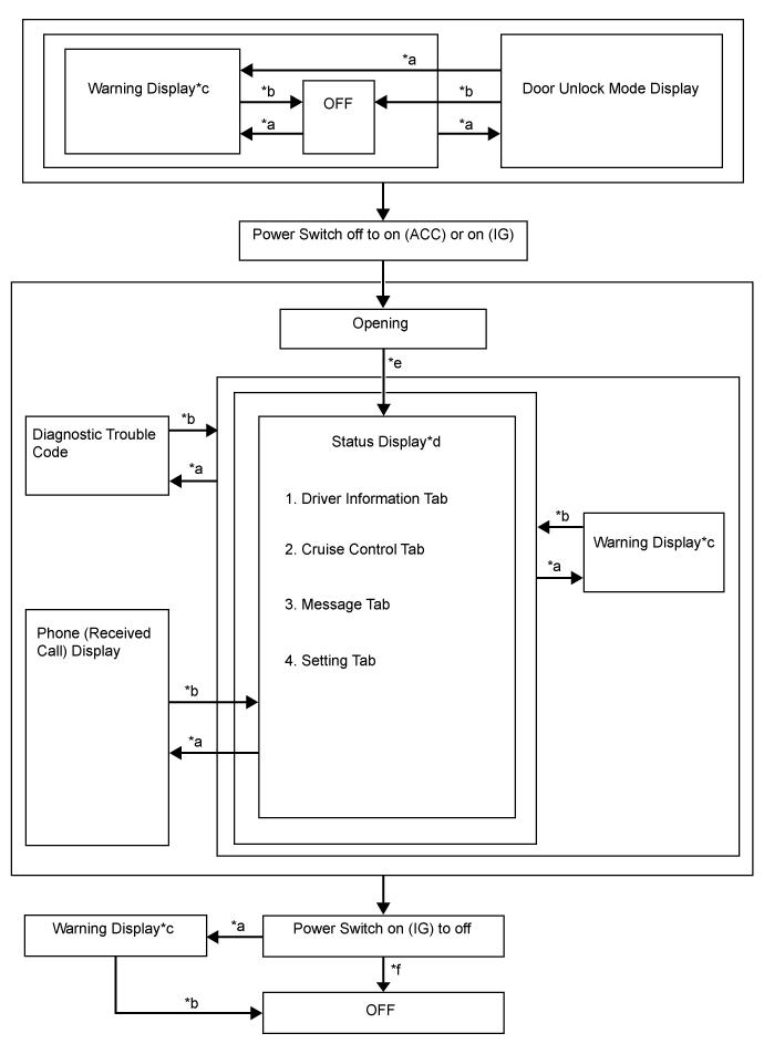
| Item | Display change condition |
| *a | Conditions are met. |
| *b | Conditions are not met. |
| *c | If there are multiple display requests, items will be displayed in sequence. |
| *d | Item or display is selected by operating the steering pad switch. |
| *e | After power switch on (IG). |
| *f | ODO display is displayed for a certain period of time after the power switch is turned off. |
| DESCRIPTION OF WARNING DISPLAYS |
| Priority | System Name/(Vehicle Function) | Master Warning Light ○: Comes on ●: Blinks | Buzzer (*1) | Display | Level |
| 1 | Hybrid control system | - | - | Maintenance Mode | Caution |
| - | - | Certification Mode | Caution | ||
| 2 | Hybrid control system | ● | * | Shift to P position when parked | Caution |
| 3 | (Each door warning (vehicle being driven)) | ● | * | Each door open (vehicle being driven) | Caution |
| (Each door warning (vehicle stopped)) | - | - | Each door open (vehicle stopped) | Caution | |
| Toyota parking assist-sensor system | - | - | Clearance sonar detection (image display) | Caution | |
| ○ | - | Check Park Sonar System | Caution | ||
| ○ | - | Clean Park Sonar | Caution | ||
| 4 | Smart entry and start system | - | - | Auto Power OFF to Conserve Battery | Caution |
| 5 | Smart entry and start system | ● | */○ | Shift to P position when parked | Caution |
| Hybrid control system | ● | * | N position | Caution | |
| ● | * | Traction battery preservation mode Restart after shifting to P position | Caution | ||
| 6 | Hybrid control system | ○ | * | Check Hybrid System Stop the vehicle in a safe place immediately | Caution |
| ● | * | Traction battery Low Charges when not in N position | Caution | ||
| (Parking brake) | ● | * | Release Parking Brake | Caution | |
| Smart entry and start system | ● | * | Key not detected | Caution | |
| 7 | Charging system | - | - | Charging System Malfunction See Owner's Manual | Caution |
| Smart entry and start system | ● | * | Check Entry & Start System | Caution | |
| Cruise control system | ○ | ○ | Check Cruise Control System | Caution | |
| (Engine oil pressure switch assembly) | ○ | ○ | Engine Oil Pressure Low | Caution | |
| 8 | Smart entry and start system | ● | */○ | Turn Power OFF | Caution |
| ● | ○ | Key detected in vehicle | Caution | ||
| Sliding roof system | ● | ○ | Moon Roof opened | Caution | |
| Smart entry and start system | ● | * | Depress brake pedal, touch POWER switch with key | Caution | |
| ● | * | Depress brake pedal and push POWER switch to start | Caution | ||
| 9 | Steering lock system | ● | * | Steering Lock active | Caution |
| Hybrid control system | ● | * | Shift to P position to start | Caution | |
| 10 | Smart entry and start system | ○ | * | Key Battery Low | Caution |
| Automatic headlight beam level control system | ○ | ○ | Check Headlight System | Caution | |
| Hybrid control system | ○ | * | Hybrid System Overheat Output Power is limited | Caution | |
| 11 | Hybrid control system | - | - | Driving force Limited | Advisory |
| Hybrid battery system | - | - | Maintenance Required for Hybrid Battery Cooling Parts at Your Dealer | Advisory | |
| Hybrid control system | - | - | Low 12-Volt Battery See Owner's Manual | Advisory | |
| (Level warning switch assembly) | - | - | Washer Fluid Low | Advisory | |
| (Fuel sender gauge assembly) | - | - | Fuel Low | Advisory | |
| Electronically controlled brake system | - | - | TRC OFF | Caution | |
| Smart entry and start system | - | - | Power ON | Caution | |
| - | - | Depress brake pedal and push POWER switch to start | Caution | ||
| Hybrid control system | - | * | EV mode currently not available | Advisory | |
| - | * | EV mode not available Warming up | Advisory | ||
| - | * | EV mode currently not available Low battery | Advisory | ||
| - | * | EV mode currently not available Excessive speed | Advisory | ||
| - | * | EV mode currently not available Excessive acceleration | Advisory | ||
| - | * | EV mode deactivated | Advisory | ||
| - | * | EV mode deactivated Low battery | Advisory | ||
| - | * | EV mode deactivated Excessive speed | Advisory | ||
| - | * | EV mode deactivated Excessive acceleration | Advisory |