 |
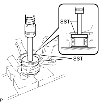
Using SST and a press, install a new front axle hub bearing to the steering knuckle.
- SST
- 09950-60020
(09951-00810)
09950-70010 (09951-07100)
FRONT AXLE HUB > INSTALLATION |
| 1. INSTALL FRONT AXLE HUB BEARING |
|
Using SST and a press, install a new front axle hub bearing to the steering knuckle.
| 2. INSTALL FRONT DISC BRAKE DUST COVER |
Install the front disc brake dust cover to the steering knuckle with the 4 bolts.
| 3. INSTALL FRONT AXLE HUB SUB-ASSEMBLY |
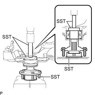 |
Using SST and a press, install the front axle hub sub-assembly to the steering knuckle.
| 4. INSTALL FRONT AXLE HUB HOLE SNAP RING |
Using snap ring pliers, install a new front axle hub hole snap ring.
| 5. INSTALL FRONT NO. 1 WHEEL BEARING DUST DEFLECTOR |
Set a new front No. 1 wheel bearing dust deflector to the steering knuckle while aligning the cutout for the speed sensor in the front No. 1 wheel bearing dust deflector with the hole of the steering knuckle.
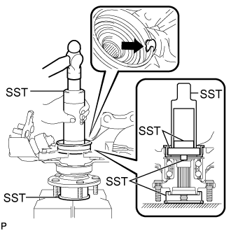 |
Using SST and a hammer, install the front No. 1 wheel bearing dust deflector.
| 6. INSTALL FRONT AXLE ASSEMBLY |
Install the front axle assembly to the front shock absorber assembly with the 2 bolts and 2 nuts.
| 7. INSTALL FRONT DRIVE SHAFT ASSEMBLY |
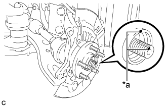 |
Align the matchmarks and install the front drive shaft assembly to the front axle hub sub-assembly.
| *a | Matchmark |
| 8. CONNECT FRONT LOWER NO. 1 SUSPENSION ARM SUB-ASSEMBLY |
Connect the front lower No. 1 suspension arm sub-assembly to the front lower ball joint assembly with the bolt and 2 nuts.
| 9. CONNECT TIE ROD ASSEMBLY |
Connect the tie rod assembly LH to the steering knuckle with the nut.
Install a new cotter pin.
| 10. INSTALL FRONT DISC |
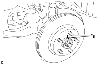 |
Align the matchmarks of the front disc and front axle hub, and install the front disc.
| *a | Matchmark |
| 11. INSTALL FRONT DISC BRAKE CALIPER ASSEMBLY |
Install the front disc brake caliper assembly to the steering knuckle with the 2 bolts.
| 12. INSTALL FRONT AXLE SHAFT NUT |
Clean the threaded parts on the front drive shaft assembly and a new front axle shaft nut using a non-residue solvent.
Using a socket wrench (30 mm), install the front axle shaft nut.
| 13. SEPARATE FRONT DISC BRAKE CALIPER ASSEMBLY |
Remove the 2 bolts and separate the front disc brake caliper assembly.
| 14. REMOVE FRONT DISC |
|
Put matchmarks on the front disc and the front axle hub.
| *a | Matchmark |
Remove the front disc.
| 15. INSPECT FRONT AXLE HUB BEARING LOOSENESS |
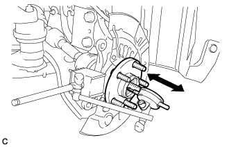 |
Using a dial indicator, check for looseness near the center of the front axle hub.
| 16. INSPECT FRONT AXLE HUB RUNOUT |
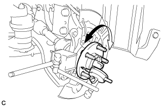 |
Using a dial indicator, check for runout on the surface of the front axle hub outside the hub bolts.
| 17. INSTALL FRONT DISC |
|
Align the matchmarks of the front disc and front axle hub, and install the front disc.
| *a | Matchmark |
| 18. INSTALL FRONT DISC BRAKE CALIPER ASSEMBLY |
Install the front disc brake caliper assembly to the steering knuckle with the 2 bolts.
| 19. INSTALL FRONT SPEED SENSOR |
Install the front speed sensor and front flexible hose to the front shock absorber assembly with the bolt and clamp.
Install the front speed sensor to the steering knuckle with the bolt.
| 20. STAKE FRONT AXLE SHAFT NUT |
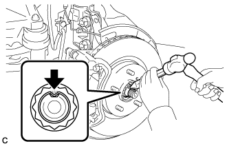 |
Using a chisel and a hammer, stake the front axle shaft nut.
| 21. INSTALL FRONT WHEEL |
| 22. CONNECT CABLE TO NEGATIVE AUXILIARY BATTERY TERMINAL |
Connect the cable to the negative (-) auxiliary battery terminal .
Connect the reservoir level switch connector.
Clear the DTCs (Click here).
| 23. INSTALL FRONT OUTER COWL TOP PANEL SUB-ASSEMBLY (for RHD) |
Install the front outer cowl top panel sub-assembly with the 10 bolts.
Engage the 2 clamps to install the wire harness to the front outer cowl top panel sub-assembly.
Engage the 2 clamps to install the wire harness to the front outer cowl top panel sub-assembly.
| 24. INSTALL WINDSHIELD WIPER MOTOR AND LINK ASSEMBLY (for RHD) |
| 25. INSPECT AND ADJUST FRONT WHEEL ALIGNMENT |
| 26. CHECK FOR SPEED SENSOR SIGNAL |