 |
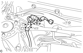
Disengage the 2 clamps and separate the wire harness from the front outer cowl top panel sub-assembly.
REAR AXLE HUB > ON-VEHICLE INSPECTION |
| 1. PRECAUTION |
| 2. REMOVE WINDSHIELD WIPER MOTOR AND LINK ASSEMBLY (for RHD) |
| 3. REMOVE FRONT OUTER COWL TOP PANEL SUB-ASSEMBLY (for RHD) |
|
Disengage the 2 clamps and separate the wire harness from the front outer cowl top panel sub-assembly.
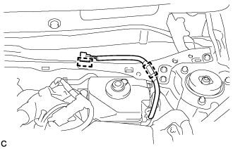 |
Disengage the 2 clamps and separate the wire harness from the front outer cowl top panel sub-assembly.
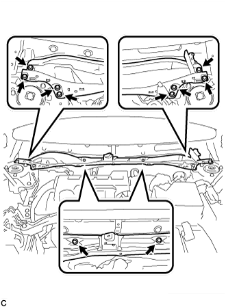 |
Remove the 10 bolts and front outer cowl top panel sub-assembly.
| 4. DISABLE BRAKE CONTROL (for LHD) |
Wait at least 2 minutes after turning the power switch off.
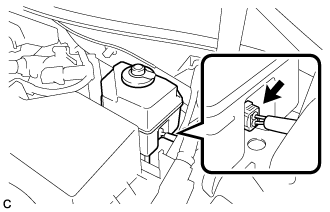 |
Disconnect the reservoir level switch connector with the parking brake applied.
Disconnect the cable from the negative (-) auxiliary battery terminal (Click here).
Depress the brake pedal 40 times or more to return all the fluid in the accumulator back to the reservoir.
Check that the brake pedal can not be further depressed.
Release the parking brake.
| 5. DISABLE BRAKE CONTROL (for RHD) |
Wait at least 2 minutes after turning the power switch off.
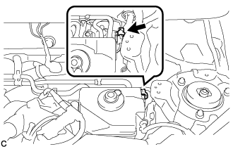 |
Disconnect the reservoir level switch connector with the parking brake applied.
Disconnect the cable from the negative (-) auxiliary battery terminal (Click here).
Depress the brake pedal 40 times or more to return all the fluid in the accumulator back to the reservoir.
Check that the brake pedal can not be further depressed.
Release the parking brake.
| 6. REMOVE REAR WHEEL |
| 7. SEPARATE REAR DISC BRAKE CALIPER ASSEMBLY |
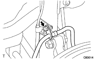 |
Remove the bolt and separate the rear flexible hose from the rear shock absorber assembly.
Remove the 2 bolts, and separate the rear disc brake caliper assembly.
| 8. REMOVE PARKING BRAKE SHOE ADJUSTING HOLE PLUG |
Remove the parking brake shoe adjusting hole plug.
| 9. REMOVE REAR DISC |
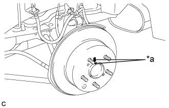 |
Put matchmarks on the rear disc and the rear axle hub.
| *a | Matchmark |
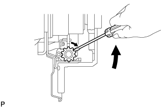 |
Release the parking brake and remove the rear disc.
| 10. INSPECT REAR AXLE HUB BEARING LOOSENESS |
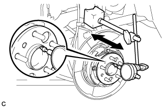 |
Using a dial indicator, check for looseness near the center of the rear axle hub.
| 11. INSPECT REAR AXLE HUB RUNOUT |
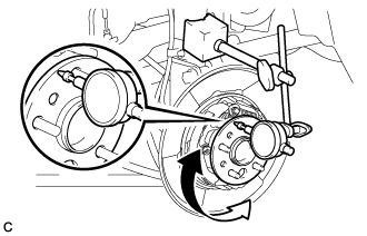 |
Using a dial indicator, check for runout on the surface of the rear axle hub outside the rear axle hub bolt.
| 12. INSTALL REAR DISC |
|
Align the matchmarks of the rear disc and rear axle hub, and install the rear disc.
| *a | Matchmark |
| 13. INSTALL PARKING BRAKE SHOE ADJUSTING HOLE PLUG |
Install the parking brake shoe adjusting hole plug.
| 14. INSTALL REAR DISC BRAKE CALIPER ASSEMBLY |
Install the rear disc brake caliper assembly with the 2 bolts.
Install the rear flexible hose to the rear shock absorber assembly with the bolt.
| 15. CONNECT CABLE TO NEGATIVE AUXILIARY BATTERY TERMINAL |
Connect the cable to the negative (-) auxiliary battery terminal .
Connect the reservoir level switch connector.
Clear the DTCs (Click here).
| 16. INSTALL FRONT OUTER COWL TOP PANEL SUB-ASSEMBLY (for RHD) |
Install the front outer cowl top panel sub-assembly with the 10 bolts.
Engage the 2 clamps to install the wire harness to the front outer cowl top panel sub-assembly.
Engage the 2 clamps to install the wire harness to the front outer cowl top panel sub-assembly.
| 17. INSTALL WINDSHIELD WIPER MOTOR AND LINK ASSEMBLY (for RHD) |
| 18. ADJUST PARKING BRAKE |
| 19. INSTALL REAR WHEEL |