 |
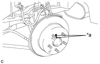
Align the matchmarks of the rear disc and rear axle hub, and install the rear disc.
| *a | Matchmark |
- NOTICE:
- When replacing the disc with a new one, select the installation position where the rear disc has minimal runout.
REAR AXLE CARRIER > INSTALLATION |
| 1. INSTALL REAR AXLE CARRIER SUB-ASSEMBLY |
Install the rear axle carrier sub-assembly to the rear shock absorber assembly with the 2 bolts and 2 nuts.
| 2. TEMPORARILY TIGHTEN REAR NO. 1 SUSPENSION ARM ASSEMBLY |
Temporarily tighten rear No. 1 suspension arm assembly (outer side) to the rear axle carrier sub-assembly with the bolt and nut.
| 3. TEMPORARILY TIGHTEN REAR NO. 2 SUSPENSION ARM ASSEMBLY |
Temporarily tighten rear No. 2 suspension arm assembly (outer side) to the rear axle carrier sub-assembly with the bolt and nut.
| 4. TEMPORARILY TIGHTEN REAR STRUT ROD ASSEMBLY |
Temporarily tighten rear strut rod assembly (rear side) to the rear axle carrier sub-assembly with the bolt and nut.
| 5. INSTALL REAR AXLE HUB AND BEARING ASSEMBLY |
Install the rear axle hub and bearing assembly and parking brake assembly to the rear axle carrier sub-assembly with the 4 bolts.
| 6. CONNECT SKID CONTROL SENSOR WIRE |
Connect the connector to the rear speed sensor.
| 7. INSTALL REAR DISC |
|
Align the matchmarks of the rear disc and rear axle hub, and install the rear disc.
| *a | Matchmark |
| 8. INSTALL PARKING BRAKE SHOE ADJUSTING HOLE PLUG |
Install the parking brake shoe adjusting hole plug.
| 9. INSTALL REAR DISC BRAKE CALIPER ASSEMBLY |
Install the rear disc brake caliper assembly with the 2 bolts.
Install the rear flexible hose to the rear shock absorber assembly with the bolt.
| 10. STABILIZE SUSPENSION |
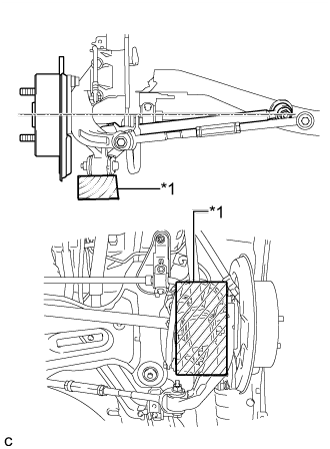 |
Jack up the rear axle carrier sub-assembly, placing a wooden block under it to avoid damage. Apply load to the suspension so that the installed bolt of the rear No. 1 suspension arm assembly (inner side) is horizontally aligned with the center of the rear axle hub.
| *1 | Wooden Block |
| 11. FULLY TIGHTEN REAR NO. 1 SUSPENSION ARM ASSEMBLY |
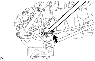 |
Fully tighten the bolt.
| 12. FULLY TIGHTEN REAR NO. 2 SUSPENSION ARM ASSEMBLY |
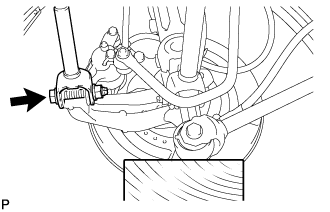 |
Fully tighten the bolt.
| 13. FULLY TIGHTEN REAR STRUT ROD ASSEMBLY |
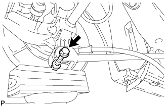 |
Fully tighten the bolt
| 14. INSTALL REAR HEIGHT CONTROL SENSOR SUB-ASSEMBLY (for RH Side) |
| 15. CONNECT CABLE TO NEGATIVE AUXILIARY BATTERY TERMINAL |
Connect the cable to the negative (-) auxiliary battery terminal .
Connect the reservoir level switch connector.
Clear the DTCs (Click here).
| 16. INSTALL FRONT OUTER COWL TOP PANEL SUB-ASSEMBLY (for RHD) |
Install the front outer cowl top panel sub-assembly with the 10 bolts.
Engage the 2 clamps to install the wire harness to the front outer cowl top panel sub-assembly.
Engage the 2 clamps to install the wire harness to the front outer cowl top panel sub-assembly.
| 17. INSTALL WINDSHIELD WIPER MOTOR AND LINK ASSEMBLY (for RHD) |
| 18. ADJUST PARKING BRAKE |
| 19. INSTALL REAR WHEEL |
| 20. INSPECT AND ADJUST REAR WHEEL ALIGNMENT |
| 21. INITIALIZE HEIGHT CONTROL SENSOR SIGNAL (for RH Side) |
| 22. INSPECT AND ADJUST HEADLIGHT AIMING (for RH Side) |
| 23. CHECK FOR SPEED SENSOR SIGNAL |