 |
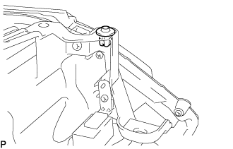
Install the grommet.
HEADLIGHT ASSEMBLY > REASSEMBLY |
| 1. INSTALL GROMMET |
|
Install the grommet.
| 2. INSTALL HEADLIGHT LEVELING MOTOR BASE PACKING |
Install a new headlight leveling motor base packing.
| 3. INSTALL HEADLIGHT LEVELING MOTOR |
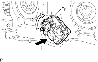 |
Insert the headlight leveling motor in the direction indicated by the arrow (1) shown in the illustration.
Turn the aiming screw of the headlight leveling motor in the direction indicated by the arrow (2) shown in the illustration to engage the shaft.
| *a | Aiming Screw |
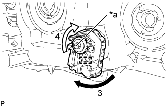 |
Turn the headlight leveling motor in the direction indicated by the arrow (3) shown in the illustration and engage the pin to install the headlight leveling motor to the headlight unit.
Turn the aiming screw of the headlight leveling motor in the direction indicated by the arrow (4) shown in the illustration.
| *a | Aiming Screw |
| 4. INSTALL FRONT TURN SIGNAL LIGHT BULB |
Install the front turn signal light bulb to the front turn signal light socket.
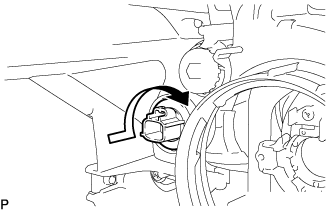 |
Turn the front turn signal light socket with the front turn signal light bulb in the direction indicated by the arrow shown in the illustration and install them as a unit.
| 5. INSTALL HEADLIGHT SOCKET COVER |
Install the headlight socket cover to the headlight unit.
| 6. INSTALL DISCHARGE HEADLIGHT BULB |
Set the discharge headlight bulb to the headlight unit.
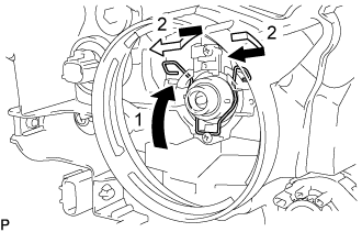 |
Lock the set spring to install the discharge headlight bulb as shown in the illustration.
| 7. INSTALL HEADLIGHT LIGHT CONTROL ECU SUB-ASSEMBLY |
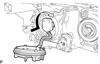 |
Turn the socket of the headlight light control ECU sub-assembly in the direction indicated by the arrow shown in the illustration to connect it.
Check that the red line on the output harness is not twisted and store the harness in the headlight assembly securely so that the output harness is not pinched.
| *a | Red Line |
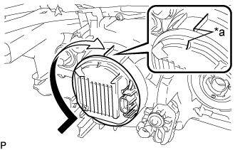 |
Turn the headlight light control ECU sub-assembly in the direction indicated by the arrow shown in the illustration until the lock marks are aligned to install it.
| *a | Lock Mark |
| 8. INSTALL NO. 1 HEADLIGHT BULB |
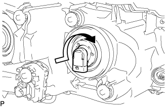 |
Turn the No. 1 headlight bulb in the direction indicated by the arrow shown in the illustration to install it.
| 9. INSTALL HEADLIGHT COVER |
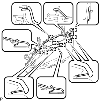 |
Engage the 8 guides and 2 claws.
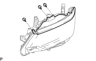 |
Install the headlight cover with the 3 screws.