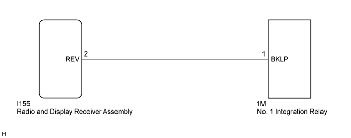
AUDIO AND VISUAL SYSTEM > Reverse Signal Circuit |
| 1.CHECK BACK-UP LIGHT |
Move the shift lever to R and check if the back-up lights come on.
|
| ||||
| OK | |
 |
| 2.CHECK HARNESS AND CONNECTOR (REVERSE SIGNAL) |
Disconnect the I155 radio and display receiver assembly connector.
Measure the voltage according to the value(s) in the table below.
| Tester Connection | Condition | Specified Condition |
| I155-2 (REV) - Body ground | Power switch on (IG) Shift lever in R | 11 to 14 V |
| I155-2 (REV) - Body ground | Power switch on (IG) Shift lever in any position other than R | Below 1 V |
|
| ||||
| OK | ||
 | ||
| ||
