 |
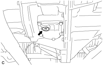
Using a hexagon wrench (10 mm), remove the drain plug indicated in the illustration and drain the coolant.
- CAUTION:
- Use caution when handling coolant immediately after driving or in summer because it may be hot.
INVERTER WITH CONVERTER > REMOVAL |
| 1. PRECAUTION |
| 2. REMOVE SERVICE PLUG GRIP |
| 3. DRAIN COOLANT (for Inverter) |
Remove the reserve tank cap.
|
Using a hexagon wrench (10 mm), remove the drain plug indicated in the illustration and drain the coolant.
Install the plug with a new gasket.
| 4. REMOVE CONNECTOR COVER ASSEMBLY |
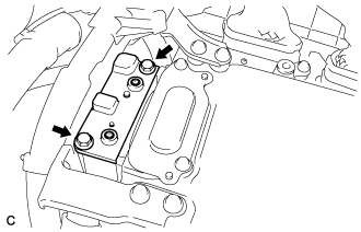 |
Remove the 2 bolts and connector cover assembly.
| 5. CHECK TERMINAL VOLTAGE |
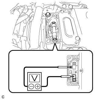 |
Using a voltmeter, measure the voltage between the terminals of the 2 phase connectors.
| 6. TEMPORARILY INSTALL CONNECTOR COVER ASSEMBLY |
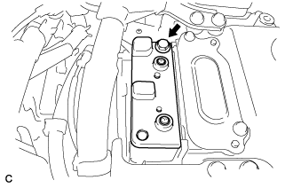 |
Temporarily install the connector cover assembly with the bolt to prevent any foreign objects or water from entering the inverter with converter assembly.
| 7. REMOVE COOL AIR INTAKE DUCT SEAL |
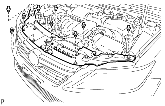 |
Remove the 9 clips and cool air intake duct seal.
| 8. REMOVE INLET AIR CLEANER ASSEMBLY |
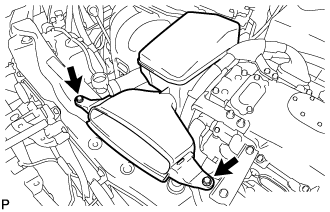 |
Remove the 2 bolts and inlet air cleaner assembly.
| 9. REMOVE AIR CLEANER CAP SUB-ASSEMBLY |
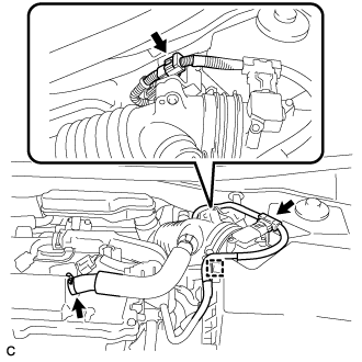 |
Disconnect the mass air flow meter connector and wire harness clamp from the air cleaner cap sub-assembly.
Disconnect the ventilation hose from the cylinder head cover.
Disconnect the connector.
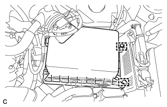 |
Release the 2 clamps and remove the air cleaner cap sub-assembly.
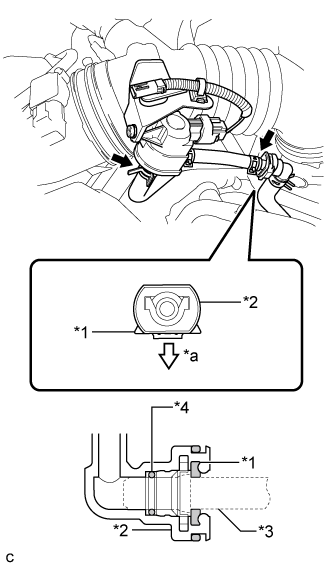 |
Disconnect the 2 fuel vapor feed hoses.
| *1 | Retainer |
| *2 | Fuel Tube Connector |
| *3 | Pipe |
| *4 | O-ring |
| *a | Pull |
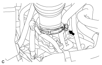 |
Loosen the hose clamp and disconnect the air cleaner hose from the throttle with motor body assembly.
| 10. REMOVE AIR CLEANER FILTER ELEMENT SUB-ASSEMBLY |
| 11. REMOVE AIR CLEANER CASE SUB-ASSEMBLY |
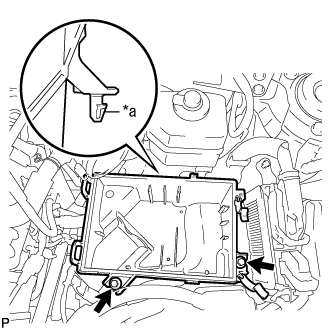 |
Remove the 2 bolts and air cleaner case sub-assembly.
| *a | Projection |
| 12. REMOVE NO. 5 INVERTER BRACKET |
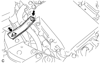 |
Remove the 2 bolts and No. 5 inverter bracket.
| 13. REMOVE NO. 4 INVERTER BRACKET |
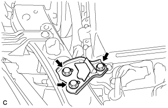 |
Remove the 3 bolts and No. 4 inverter bracket.
| 14. REMOVE UPPER INVERTER COVER |
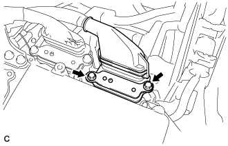 |
Remove the 2 bolts and upper inverter cover (generator cable side).
| 15. DISCONNECT GENERATOR CABLE |
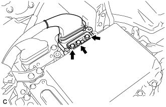 |
Using an insulated tool, remove the 3 bolts.
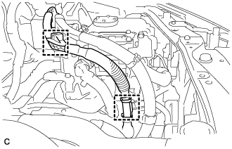 |
Disconnect the 2 wire harness clamps and separate the generator cable.
| 16. REMOVE UPPER INVERTER COVER |
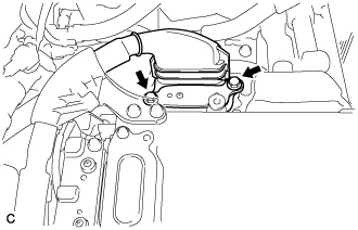 |
Remove the 2 bolts and upper inverter cover (motor cable side).
| 17. DISCONNECT MOTOR CABLE |
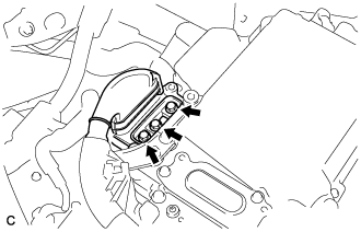 |
Using an insulated tool, remove the 3 bolts.
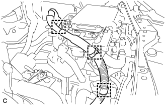 |
Disconnect the 3 wire harness clamps and separate the motor cable.
| 18. REMOVE NO. 3 MOTOR CABLE BRACKET |
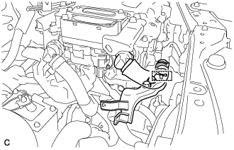 |
Disconnect the hose clamp from the No. 3 motor cable bracket.
Remove the 2 bolts and No. 3 motor cable bracket.
| 19. REMOVE CONNECTOR COVER ASSEMBLY |
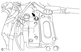 |
Remove the bolt and connector cover assembly.
| 20. DISCONNECT NO. 4 ENGINE WIRE |
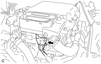 |
Disconnect the No. 4 engine wire.
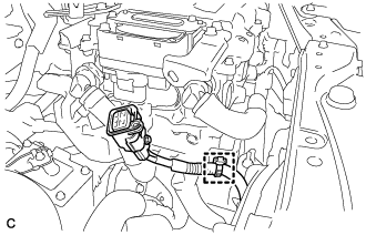 |
Disconnect the wire harness clamp.
| 21. DISCONNECT NO. 4 FLOOR WIRE |
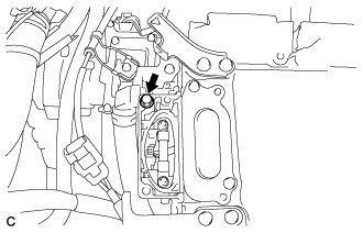 |
Remove the bolt.
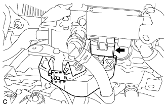 |
Disconnect the wire harness clamp and connector.
| 22. TEMPORARILY INSTALL CONNECTOR COVER ASSEMBLY |
|
Temporarily install the connector cover assembly with the bolt to prevent any foreign objects or water from entering the inverter with converter assembly.
| 23. DISCONNECT LOW VOLTAGE CONNECTOR |
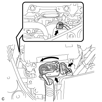 |
Raise the lock lever and disconnect the 3 low voltage connectors.
Disconnect the low voltage connector from the inverter with converter assembly.
| 24. DISCONNECT NO. 3 ENGINE ROOM WIRE |
Remove the relay block cover.
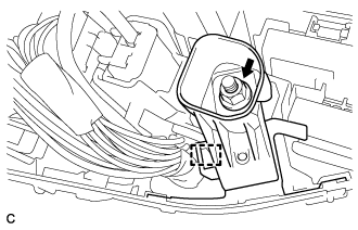 |
Remove the nut.
Disconnect the wire harness clamp and No. 3 engine room wire.
| 25. REMOVE NO. 4 INVERTER COOLING HOSE |
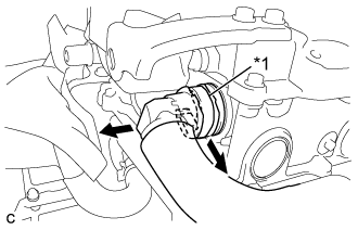 |
Release the retainer and disconnect the No. 4 inverter cooling hose from the inverter with converter assembly.
| *1 | Retainer |
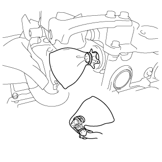 |
Put pieces of cloth into the pipes and in the disconnected hoses, or cover the pipes and hoses with plastic bags as shown in the illustration to prevent foreign matter from entering the cooling system and to prevent coolant from spilling near the inverter with converter assembly.
| 26. REMOVE NO. 1 INVERTER COOLING HOSE ASSEMBLY |
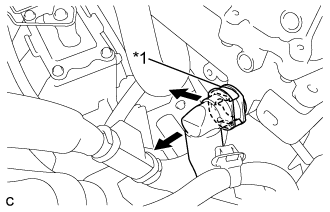 |
Release the retainer and disconnect the No. 1 inverter cooling hose from the inverter with converter assembly.
| *1 | Retainer |
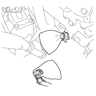 |
Put pieces of cloth into the pipes and in the disconnected hoses, or cover the pipes and hoses with plastic bags as shown in the illustration to prevent foreign matter from entering the cooling system and to prevent coolant from spilling near the inverter with converter assembly.
| 27. REMOVE INVERTER WITH CONVERTER ASSEMBLY |
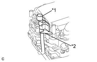 |
Temporarily secure the No. 3 engine room wire with the inverter with converter assembly hook as shown in the illustration.
| *1 | No. 3 Engine Room Wire |
| *2 | Hook |
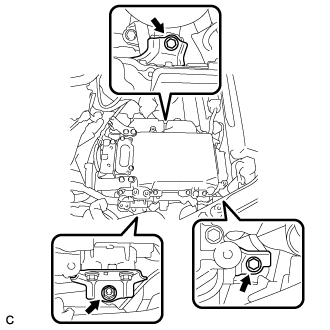 |
Remove the 2 bolts, nut and inverter with converter assembly.
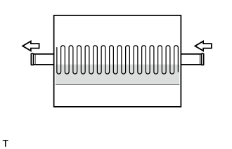 |
Even after the coolant is drained, coolant remains in the inverter with converter assembly due to its internal structure. Therefore, seal or cover the pipes when removing the inverter with converter to prevent coolant from spilling out or foreign matter from entering the inverter with converter.
| 28. REMOVE HIGH VOLTAGE FUSE |
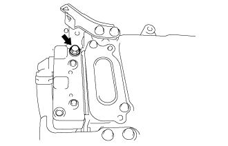 |
Remove the bolt and connector cover assembly.
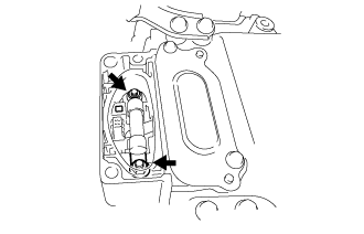 |
Remove the 2 nuts and high voltage fuse.
|
Temporarily install the connector cover assembly with the bolt to prevent any foreign objects or water from entering the inverter with converter assembly.
| 29. REMOVE AIR CLEANER BRACKET |
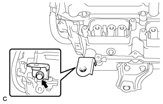 |
Remove the bolt and air cleaner bracket.
| 30. REMOVE AIR CLEANER BRACKET |
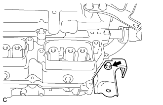 |
Remove the bolt and air cleaner bracket.
| 31. REMOVE NO. 1 INVERTER BRACKET |
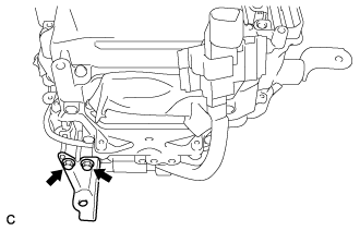 |
Remove the 2 bolts and No. 1 inverter bracket.
| 32. REMOVE NO. 2 INVERTER BRACKET |
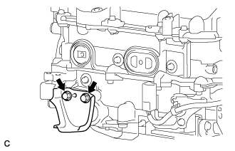 |
Remove the 2 bolts and No. 2 inverter bracket.
| 33. REMOVE NO. 3 INVERTER BRACKET |
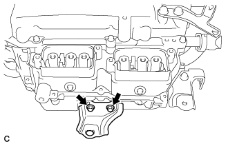 |
Remove the 2 bolts and No. 3 inverter bracket.
| 34. REMOVE NO. 1 MOTOR CABLE BRACKET |
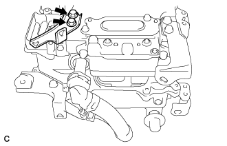 |
Remove the 2 bolts and No. 1 motor cable bracket.
| 35. REMOVE NO. 2 MOTOR CABLE BRACKET |
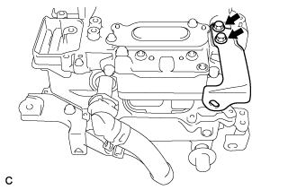 |
Remove the 2 bolts and No. 2 motor cable bracket.
| 36. REMOVE NO. 1 INVERTER COOLING HOSE |
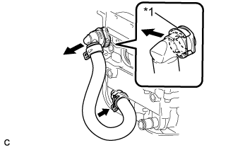 |
Release the retainer and disconnect the No. 1 inverter cooling hose from the inverter with converter assembly.
| *1 | Retainer |
Remove the No. 1 inverter cooling hose.
|
Put pieces of cloth into the pipes and in the disconnected hoses, or cover the pipes and hoses with plastic bags as shown in the illustration to prevent foreign matter from entering the cooling system and to prevent coolant from spilling near the inverter with converter assembly.
| 37. REMOVE NO. 3 ENGINE ROOM WIRE |
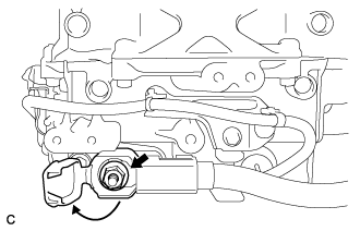 |
Open the cover.
Remove the nut and No. 3 engine room wire.