| B |  |
| GO TO DTC CHART (HYBRID CONTROL SYSTEM) (Click here) |
DTC P0A51-174 Drive Motor "A" Current Sensor Circuit |
| DTC No. | INF Code | DTC Detection Condition | Trouble Area |
| P0A51 | 174 | Motor current sensor high resolution circuit signal is out of range or there is a difference between it and the motor current sensor low resolution circuit current value. | Inverter with converter assembly |
| 1.CHECK DTC OUTPUT (HYBRID CONTROL) |
Connect the intelligent tester to the DLC3.
Turn the power switch on (IG).
Enter the following menus: Powertrain / Hybrid Control / DTC.
Check if DTCs are output.
| Result | Proceed to |
| P0A51-174 only is output. | A |
| Any of the following DTCs are also output. | B |
| DTC No. | Relevant Diagnosis |
| P0A1B-505 | Drive Motor "A" Control Module |
| P0A40-506 | Drive Motor "A" Position Sensor Circuit Range/Performance |
| P0A78-113, 287 | Drive Motor "A" Inverter Performance |
| P0BEA-290 | Drive Motor "A" Phase V Current Sensor Circuit Range/Performance |
| P0BEE-298 | Drive Motor "A" Phase W Current Sensor Circuit Range/Performance |
| P1C3C-294 | Drive Motor "A" Phase V Current Sensor Correlation |
| P1C3D-302 | Drive Motor "A" Phase W Current Sensor Correlation |
| P1C4A-288 | Drive Motor "A" Phase V Current Sensor Sub Circuit Range/Performance |
| P1C4F-296 | Drive Motor "A" Phase W Current Sensor Sub Circuit Range/Performance |
| P1C6D-501 | Drive Motor "A" Phase V Current Sensor Offset Range/Performance |
| P1C6E-502 | Drive Motor "A" Phase W Current Sensor Offset Range/Performance |
Turn the power switch off.
|
| ||||
| A | |
 |
| 2.CHECK CONNECTOR CONNECTION CONDITION (INVERTER WITH CONVERTER ASSEMBLY CONNECTOR) |
Check that the service plug grip is not installed.
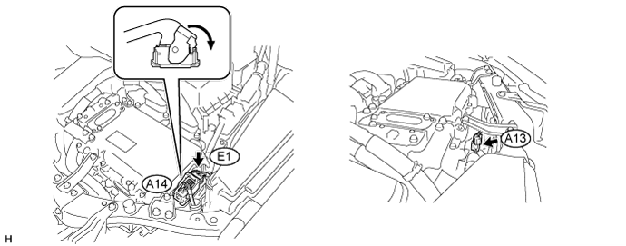
Check the connector connections and contact pressure of the low voltage connectors of the inverter with converter assembly (Click here).
|
| ||||
| OK | ||
 | ||
| ||