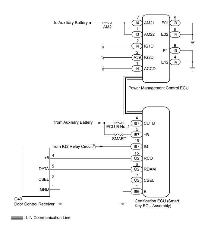
SMART ENTRY AND START SYSTEM (for Entry Function) > All Door Entry Lock/Unlock Functions and Wireless Functions do not Operate |
| 1.INSPECT AUXILIARY BATTERY VOLTAGE |
Measure the voltage of the vehicle auxiliary battery.
| NEXT | |
 |
| 2.CHECK FOR DTC |
Open the driver door using the mechanical key built into the electrical key transmitter sub-assembly.
Connect the intelligent tester and check for DTCs (Click here).
|
| ||||
| OK | |
|
| 3.CHECK POWER DOOR LOCK CONTROL SYSTEM |
When the door control switch on the multiplex network master switch assembly on the driver door is operated, check that the doors unlock and lock according to the switch operation (Click here).
|
| ||||
| OK | |
|
| 4.CHECK KEY DIAGNOSTIC MODE |
Check the following antennas in the key diagnostic mode (Click here).
Select either channel 1 or channel 2 and inspect the key diagnostic mode for each channel.
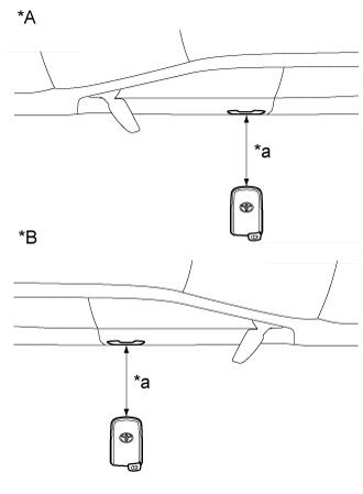 |
Check the electrical key antenna (for driver door):
| *A | for LHD |
| *B | for RHD |
| *a | 0.7 to 1 m (2.30 to 3.28 ft.) |
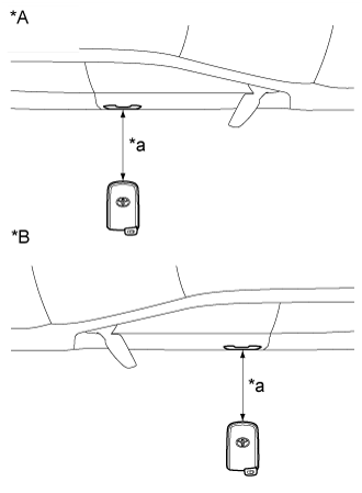 |
Check the electrical key antenna (for front passenger door):
| *A | for LHD |
| *B | for RHD |
| *a | 0.7 to 1 m (2.30 to 3.28 ft.) |
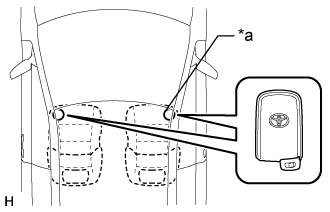 |
Check the No. 1 indoor electrical key antenna (front floor):
| *a | Inspection Point |
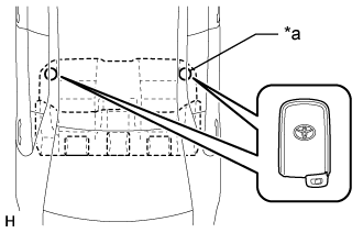 |
Check the No. 2 indoor electrical key antenna (rear floor):
| *a | Inspection Point |
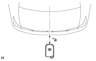 |
Check the electrical key antenna (outside luggage):
| *a | 0.7 to 1 m (2.30 to 3.28 ft.) |
| Result | Proceed to |
| Diagnostic mode inspections fail for both channels | A |
| Diagnostic mode inspections succeed for both channels | B |
| Diagnostic mode inspection succeeds for only one of the channels | C |
|
| ||||
|
| ||||
| A | |
|
| 5.CHECK ELECTRICAL KEY TRANSMITTER SUB-ASSEMBLY |
Check if there are any other registered electrical key transmitter sub-assemblies.
| Result | Proceed to |
| There are no other registered electrical key transmitter sub-assemblies | A |
| There is another registered electrical key transmitter sub-assemblies | B |
|
| ||||
| A | |
|
| 6.ELECTRICAL KEY TRANSMITTER SUB-ASSEMBLY REGISTRATION (NEW ELECTRICAL KEY TRANSMITTER SUB-ASSEMBLY) |
Register a new electrical key transmitter sub-assembly.
| NEXT | |
|
| 7.CHECK ENTRY DOOR LOCK OPERATION |
Using another registered electrical key transmitter sub-assembly, check if an entry lock/unlock operation can be performed twice in succession.
|
| ||||
| OK | |
|
| 8.CHECK TRANSMITTER BATTERY |
Check the transmitter battery level of the electrical key transmitter sub-assembly that was checked first.
Press and hold the lock switch of the transmitter for 5 seconds and check the number of times that the transmitter LED illuminates.
| Result | Proceed to |
| Transmitter LED does not illuminate when switch is pressed and held | A |
| Transmitter LED illuminates 3 times or more when switch is pressed and held | B |
| Transmitter LED illuminates once or twice but not a third time | C |
|
| ||||
|
| ||||
| A | |
|
| 9.INSPECT TRANSMITTER BATTERY (VOLTAGE) |
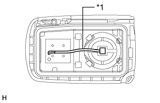
Inspect the transmitter battery
 |
Remove the transmitter battery from the electrical key transmitter sub-assembly that does not operate (Click here).
Attach a lead wire (0.60 mm (0.0236 in.) in diameter or less including wire sheath) with tape or equivalent to the negative terminal.
| *1 | Lead Wire |
Carefully pull the lead wire out from the position shown in the illustration and install the previously removed transmitter battery.
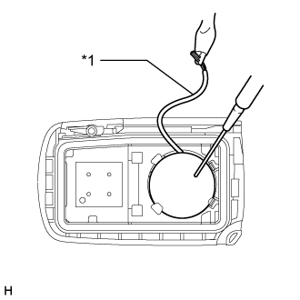 |
Measure the voltage of the transmitter battery.
| *1 | GND |
| Tester Connection | Condition | Specified Condition |
| Transmitter battery positive (+) - Transmitter battery negative (-) | Power switch off, all doors closed and lock sensor touched | 2.3 to 3.2 V |
|
| ||||
| OK | ||
 | ||
| ||
| 10.CHECK WAVE ENVIRONMENT |
Bring the electrical key transmitter sub-assembly near the door control receiver and perform a wireless and entry function operation check.
|
| ||||
| OK | ||
| ||
| ||
| 11.READ VALUE USING INTELLIGENT TESTER (ACC SW, IG SW) |
Connect the intelligent tester to the DLC3.
Turn the power switch on (IG).
Turn the intelligent tester on.
Enter the following menus: Body / Main Body / Data List.
Read the Data List according to the display on the intelligent tester.
| Tester Display | Measurement Item/Range | Normal Condition | Diagnostic Note |
| ACC SW | Power switch status / ON or OFF | ON: Power switch on (ACC) OFF: Power switch off | - |
| IG SW | Power switch status / ON or OFF | ON: Power switch to ON OFF: Power switch off | - |
|
| ||||
| OK | |
|
| 12.CHECK HARNESS AND CONNECTOR (CERTIFICATION ECU - AUXILIARY BATTERY AND BODY GROUND) |
Disconnect the I86 and I87 certification ECU (smart key ECU assembly) connectors.
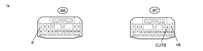
Measure the resistance according to the value(s) in the table below.
| Tester Connection | Condition | Specified Condition |
| I86-1 (E) - Body ground | Always | Below 1 Ω |
Measure the voltage according to the value(s) in the table below.
| Tester Connection | Condition | Specified Condition |
| I87-4 (CUTB) - Body ground | Always | 11 to 14 V |
| I87-5 (+B) - Body ground | Always | 11 to 14 V |
| *a | Front view of wire harness connector (to Certification ECU (Smart Key ECU Assembly)) |
|
| ||||
| OK | |
|
| 13.CHECK HARNESS AND CONNECTOR (CERTIFICATION ECU - DOOR CONTROL RECEIVER) |
Disconnect the O2 certification ECU (smart key ECU assembly) connector.
Disconnect the O43 door control receiver connector.
Measure the resistance according to the value(s) in the table below.
| Tester Connection | Condition | Specified Condition |
| O2-15 (RCO) - O43-4 (+5) | Always | Below 1 Ω |
| O2-6 (RDAM) - O43-5 (DATA) | Always | Below 1 Ω |
| O2-7 (CSEL) - O43-2 (CSEL) | Always | Below 1 Ω |
| O2-15 (RCO) or O43-4 (+5) - Body ground | Always | 10 kΩ or higher |
| O2-6 (RDAM) or O43-5 (DATA) - Body ground | Always | 10 kΩ or higher |
| O2-7 (CSEL) or O43-2 (CSEL) - Body ground | Always | 10 kΩ or higher |
|
| ||||
| OK | |
|
| 14.CHECK DOOR CONTROL RECEIVER |
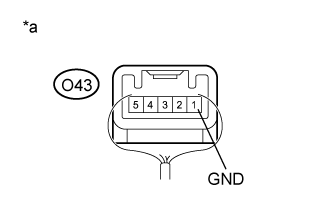 |
Connect the O43 door control receiver connector.
Connect the O2 certification ECU (smart key ECU assembly) connector.
Measure the resistance according to the value(s) in the table below.
| Tester Connection | Condition | Specified Condition |
| O43-1 (GND) - Body ground | Always | Below 1 Ω |
| *a | Component with harness connected (Door Control Receiver) |
|
| ||||
| OK | |
|
| 15.CHECK CERTIFICATION ECU (SMART KEY ECU ASSEMBLY) |
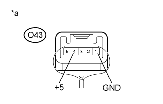 |
Connect the O2 certification ECU (smart key ECU assembly) connector.
Connect the O43 door control receiver connector.
Measure the voltage according to the value(s) in the table below.
| Tester Connection | Condition | Specified Condition |
| O43-4 (+5) - O43-1 (GND) | Procedure:
| Below 1 V |
Procedure:
| 4.5 to 5.5 V |
| *a | Component with harness connected (Door Control Receiver) |
|
| ||||
| OK | |
|
| 16.CHECK DOOR CONTROL RECEIVER |
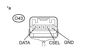 |
Connect the O2 certification ECU (smart key ECU assembly) connector.
Connect the O43 door control receiver connector.
Measure the voltage according to the value(s) in the table below.
| Tester Connection | Condition | Specified Condition |
| O43-5 (DATA) - O43-1 (GND) | Procedure:
| Below 1 V → 11 to 14 V → Below 1 V |
| O43-2 (CSEL) - O43-1 (GND) | Procedure:
| Below 1 V → 4.4 to 6.5 V → Below 1 V |
| *a | Component with harness connected (Door Control Receiver) |
|
| ||||
| OK | |
|
| 17.REPLACE CERTIFICATION ECU (SMART KEY ECU ASSEMBLY) |
Temporarily replace the certification ECU (smart key ECU assembly) with a new one.
| NEXT | |
|
| 18.CHECK WIRELESS DOOR LOCK CONTROL SYSTEM |
Check that the wireless door lock functions operate normally (Click here).
|
| ||||
| OK | ||
| ||
| ||
| 19.CHECK WAVE ENVIRONMENT |
Bring the electrical key transmitter sub-assembly that was checked first near the door control receiver and select the failed channel (the channel in which the buzzer did not sound) to recheck the key diagnostic mode (Click here).
|
| ||||
| OK | ||
| ||
| ||
| 20.CHECK ELECTRICAL KEY TRANSMITTER SUB-ASSEMBLY |
Check if there are any other registered electrical key transmitter sub-assemblies.
| Result | Proceed to |
| There are no other registered electrical key transmitter sub-assemblies | A |
| There is another registered electrical key transmitter sub-assemblies | B |
|
| ||||
| A | |
|
| 21.ELECTRICAL KEY TRANSMITTER SUB-ASSEMBLY REGISTRATION (NEW ELECTRICAL KEY TRANSMITTER SUB-ASSEMBLY) |
Register a new electrical key transmitter sub-assembly.
| NEXT | |
|
| 22.CHECK WAVE ENVIRONMENT |
Bring another registered electrical key transmitter sub-assembly near the door control receiver and select the failed channel (the channel in which the buzzer did not sound) to recheck the key diagnostic mode (Click here).
|
| ||||
| OK | ||
| ||
| ||
| 23.CHECK HARNESS AND CONNECTOR (CERTIFICATION ECU - DOOR CONTROL RECEIVER) |
Disconnect the O2 certification ECU (smart key ECU assembly) connector.
Disconnect the O43 door control receiver connector.
Measure the resistance according to the value(s) in the table below.
| Tester Connection | Condition | Specified Condition |
| O2-7 (CSEL) - O43-2 (CSEL) | Always | Below 1 Ω |
| O2-7 (CSEL) or O43-2 (CSEL) - Body ground | Always | 10 kΩ or higher |
|
| ||||
| OK | |
|
| 24.CHECK CERTIFICATION ECU (SMART KEY ECU ASSEMBLY) |
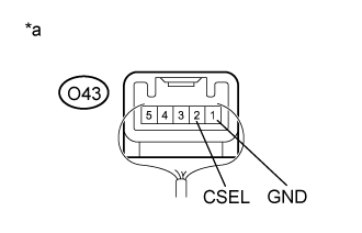 |
Connect the O2 certification ECU (smart key ECU assembly) connector.
Connect the O43 door control receiver connector.
Measure the voltage according to the value(s) in the table below.
| Tester Connection | Condition | Specified Condition |
| O43-2 (CSEL) - O43-1 (GND) | Power switch off and all doors closed | Below 1 V → 4.4 to 6.5 V → Below 1 V |
| *a | Component with harness connected (Door Control Receiver) |
|
| ||||
| OK | |
|
| 25.CHECK DOOR CONTROL RECEIVER |
Connect the O2 certification ECU (smart key ECU assembly) connector.
Connect the O43 door control receiver connector.
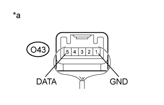 |
Measure the voltage according to the value(s) in the table below.
| Tester Connection | Condition | Specified Condition |
| O43-5 (DATA) - O43-1 (GND) | Procedure:
| Below 1 V → 11 to 14 V → Below 1 V |
| *a | Component with harness connected (Door Control Receiver) |
|
| ||||
| OK | |
|
| 26.REPLACE CERTIFICATION ECU (SMART KEY ECU ASSEMBLY) |
Temporarily replace the certification ECU (smart key ECU assembly) with a new one.
| NEXT | |
|
| 27.CHECK WIRELESS DOOR LOCK CONTROL SYSTEM |
Check that the wireless door lock functions operate normally (Click here).
|
| ||||
| OK | ||
| ||
| ||

