Home › Brake › BRAKE CONTROL / DYNAMIC CONTROL SYSTEMS › REAR SPEED SENSOR

REAR SPEED SENSOR > INSTALLATION

for Preparation Click here


HINT:
  1. Use the same procedure for the LH side and RH side.
  2. The following procedure is for the LH side.
  3. If the sensor rotor needs to be replaced, replace the rear axle hub and bearing assembly.
  4. The rear speed sensor is a component of the rear axle hub and bearing assembly. If the rear speed sensor malfunctions, replace the rear axle hub and bearing assembly.


1. INSTALL REAR AXLE HUB AND BEARING ASSEMBLY
  1. Install the rear axle hub and bearing assembly .

    HINT:
    1. The rear speed sensor is a component of the rear axle hub and bearing assembly. If the sensor malfunctions, replace the rear axle hub and bearing assembly.
    2. If the sensor rotor needs to be replaced, replace the rear axle hub and bearing assembly.


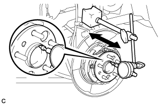
2. INSPECT REAR AXLE HUB BEARING LOOSENESS


    C240543
  1. Using a dial indicator, check for looseness near the center of the rear axle hub.

    Maximum looseness:
    0.05 mm (0.00197 in.)

    NOTICE:
    1. Ensure that the dial indicator is set perpendicular to the measurement surface.
    2. Keep the magnet of the dial indicator away from the rear axle hub and bearing assembly.

    If the looseness exceeds the maximum, replace the rear axle hub and bearing assembly.


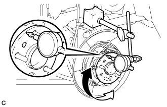
3. INSPECT REAR AXLE HUB RUNOUT


    C240542
  1. Using a dial indicator, check for runout on the surface of the rear axle hub outside the rear axle hub bolt.

    Maximum runout:
    0.07 mm (0.00276 in.)

    NOTICE:
    1. Ensure that the dial indicator is set perpendicular to the measurement surface.
    2. Make sure to install the tip of the dial indicator towards the outside of the rear axle hub bolt.
    3. Keep the magnet of the dial indicator away from the rear axle hub and bearing assembly.

    If the runout exceeds the maximum, replace the rear axle hub and bearing assembly.


4. CONNECT SKID CONTROL SENSOR WIRE
  1. Connect the connector to the rear speed sensor.


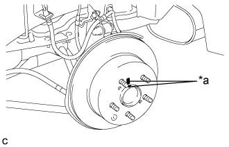
5. INSTALL REAR DISC


    C238505E01
  1. Align the matchmarks of the rear disc and rear axle hub, and install the rear disc.
    Text in Illustration 
    *a
    Matchmark

    NOTICE:
    When replacing the disc with a new one, select the installation position where the rear disc has minimal runout.


6. INSTALL PARKING BRAKE SHOE ADJUSTING HOLE PLUG
  1. Install the parking brake shoe adjusting hole plug.


7. INSTALL REAR DISC BRAKE CALIPER ASSEMBLY
  1. Install the rear disc brake caliper assembly with the 2 bolts.

    Torque:
    62 N*m{ 630 kgf*cm , 46 ft.*lbf }

  1. Install the rear flexible hose to the rear shock absorber assembly with the bolt.

    Torque:
    19 N*m{ 192 kgf*cm , 14 ft.*lbf }


8. CONNECT CABLE TO NEGATIVE AUXILIARY BATTERY TERMINAL
  1. Connect the cable to the negative (-) auxiliary battery terminal .

  1. Connect the reservoir level switch connector.

  1. Clear the DTCs (Click here).


9. INSTALL FRONT OUTER COWL TOP PANEL SUB-ASSEMBLY (for RHD)
  1. Install the front outer cowl top panel sub-assembly with the 10 bolts.

    Torque:
    10 N*m{ 102 kgf*cm , 7 ft.*lbf }

  1. Engage the 2 clamps to install the wire harness to the front outer cowl top panel sub-assembly.

  1. Engage the 2 clamps to install the wire harness to the front outer cowl top panel sub-assembly.


10. INSTALL WINDSHIELD WIPER MOTOR AND LINK ASSEMBLY (for RHD)


11. ADJUST PARKING BRAKE
(Click here)


12. INSTALL REAR WHEEL

Torque:
103 N*m{ 1049 kgf*cm , 76 ft.*lbf }


13. CHECK FOR SPEED SENSOR SIGNAL
(Click here)