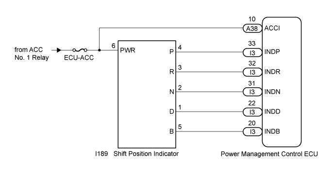
HYBRID CONTROL SYSTEM > Indicator Circuit |
| 1.CHECK SHIFT POSITION INDICATOR |
Turn the power switch on (ACC).
Check that each shift position indicator light turns on correctly.
| Result | Proceed to |
| All shift position indicator lights turn on simultaneously | A |
| Shift position indicator lights other than corresponding one turn on | A |
| Corresponding shift position indicator light does not turn on | B |
| No shift position indicator lights turn on | B |
Turn the power switch off.
|
| ||||
| A | |
 |
| 2.CHECK HARNESS AND CONNECTOR (CHECK FOR SHORT TO GND) |
Disconnect the I3 power management control ECU connector.
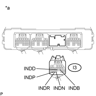 |
Measure the resistance according to the value(s) in the table below.
| Tester Connection | Condition | Specified Condition |
| I3-33 (INDP) - Body ground and other terminals | Power switch off | 10 kΩ or higher |
| I3-32 (INDR) - Body ground and other terminals | Power switch off | 10 kΩ or higher |
| I3-31 (INDN) - Body ground and other terminals | Power switch off | 10 kΩ or higher |
| I3-22 (INDD) - Body ground and other terminals | Power switch off | 10 kΩ or higher |
| I3-20 (INDB) - Body ground and other terminals | Power switch off | 10 kΩ or higher |
| *a | Rear view of wire harness connector (to Power Management Control ECU) |
| Result | Proceed to |
| OK | A |
| NG | B |
Reconnect the I3 power management control ECU connector.
|
| ||||
| A | ||
 | ||
| ||
| 3.CHECK HARNESS AND CONNECTOR (POWER MANAGEMENT CONTROL ECU - SHIFT POSITION INDICATOR) |
Disconnect the I3 power management control ECU connector.
Disconnect the I189 shift position indicator connector.
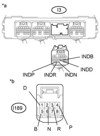 |
Measure the resistance according to the value(s) in the table below.
| Tester Connection | Condition | Specified Condition |
| I3-33 (INDP) or I189-4 (P) - Body ground and other terminals | Always | 10 kΩ or higher |
| I3-32 (INDR) or I189-3 (R) - Body ground and other terminals | Always | 10 kΩ or higher |
| I3-31 (INDN) or I189-2 (N) - Body ground and other terminals | Always | 10 kΩ or higher |
| I3-22 (INDD) or I189-1 (D) - Body ground and other terminals | Always | 10 kΩ or higher |
| I3-20 (INDB) or I189-5 (B) - Body ground and other terminals | Always | 10 kΩ or higher |
| *a | Rear view of wire harness connector (to Power Management Control ECU) |
| *b | Front view of wire harness connector (to Shift Position Indicator) |
Reconnect the I189 shift position indicator connector.
Reconnect the I3 power management control ECU connector.
|
| ||||
| OK | ||
| ||
| ||
| 4.CHECK FUSE (ECU-ACC) |
Remove the ECU-ACC fuse from the instrument panel junction block assembly.
Measure the resistance according to the value(s) in the table below.
| Tester Connection | Condition | Specified Condition |
| ECU-ACC fuse | Always | Below 1 Ω |
Install the ECU-ACC fuse.
|
| ||||
| OK | |
|
| 5.CHECK HARNESS AND CONNECTOR (POWER SOURCE CIRCUIT) |
Disconnect the I189 shift position indicator connector.
Turn the power switch on (ACC).
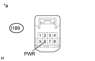 |
Measure the voltage according to the value(s) in the table below.
| Tester Connection | Condition | Specified Condition |
| H189-6 (PWR) - Body ground | Power switch on (ACC) | 11 to 14 V |
| *a | Front view of wire harness connector (to Shift Position Indicator) |
Turn the power switch off.
Reconnect the I189 shift position indicator connector.
|
| ||||
| OK | |
|
| 6.CHECK HARNESS AND CONNECTOR (POWER SOURCE TERMINAL ACCI) |
Turn the power switch on (ACC).
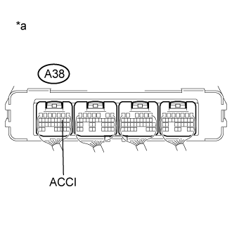 |
Measure the voltage according to the value(s) in the table below.
| Tester Connection | Condition | Specified Condition |
| A38-10 (ACCI) - Body ground | Power switch on (ACC) | 11 to 14 V |
| *a | Component with harness connected (Power Management Control ECU) |
Turn the power switch off.
|
| ||||
| OK | |
|
| 7.CHECK HARNESS AND CONNECTOR (CHECK FOR OPEN) |
Disconnect the I3 power management control ECU connector.
Turn the power switch on (ACC).
|
Measure the voltage according to the value(s) in the table below.
| Tester Connection | Condition | Specified Condition |
| I3-33 (INDP) - Body ground and other terminals | Power switch on (ACC) | 11 to 14 V |
| I3-32 (INDR) - Body ground and other terminals | Power switch on (ACC) | 11 to 14 V |
| I3-31 (INDN) - Body ground and other terminals | Power switch on (ACC) | 11 to 14 V |
| I3-22 (INDD) - Body ground and other terminals | Power switch on (ACC) | 11 to 14 V |
| I3-20 (INDB) - Body ground and other terminals | Power switch on (ACC) | 11 to 14 V |
| *a | Rear view of wire harness connector (to Power Management Control ECU) |
| Result | Proceed to |
| OK | A |
| NG | B |
Turn the power switch off.
Reconnect the I3 power management control ECU connector.
|
| ||||
| A | ||
| ||
| ||
| 8.CHECK HARNESS AND CONNECTOR (POWER MANAGEMENT CONTROL ECU - SHIFT POSITION INDICATOR) |
Disconnect the I3 power management control ECU connector.
Disconnect the H189 shift position indicator connector.
|
Measure the resistance according to the value(s) in the table below.
| Tester Connection | Condition | Specified Condition |
| I3-33 (INDP) - I189-4 (P) | Always | Below 1 Ω |
| I3-32 (INDR) - I189-3 (R) | Always | Below 1 Ω |
| I3-31 (INDN) - I189-2 (N) | Always | Below 1 Ω |
| I3-22 (INDD) - I189-1 (D) | Always | Below 1 Ω |
| I3-20 (INDB) - I189-5 (B) | Always | Below 1 Ω |
| *a | Rear view of wire harness connector (to Power Management Controll ECU) |
| *b | Front view of wire harness connector (to Shift Position Indicator) |
Reconnect the I189shift position indicator connector.
Reconnect the I3 power management control ECU connector.
|
| ||||
| OK | ||
| ||
| ||

