 |
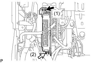
Install the power management control ECU with the 2 nuts in the order shown in the illustration.
- Torque:
- 7.5 N*m{ 76 kgf*cm , 66 in.*lbf }
POWER MANAGEMENT CONTROL ECU > INSTALLATION |
| 1. INSTALL POWER MANAGEMENT CONTROL ECU |
|
Install the power management control ECU with the 2 nuts in the order shown in the illustration.
Connect the 4 connectors.
| 2. INSTALL LOWER INSTRUMENT PANEL SUB-ASSEMBLY (for RHD) |
| 3. INSTALL NO. 2 INSTRUMENT PANEL UNDER COVER SUB-ASSEMBLY (for RHD) |
| 4. INSTALL INSTRUMENT PANEL SUB-ASSEMBLY (for LHD) |
Engage the 5 clips and 3 guides.
Install the instrument panel sub-assembly with the 2 bolts <B>.
| 5. CONNECT HOOD LOCK CONTROL LEVER SUB-ASSEMBLY (for LHD) |
Engage the claw and 2 guides to connect the hood lock control lever sub-assembly.
| 6. INSTALL INSTRUMENT SIDE PANEL LH |
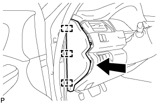 |
Engage the 3 guides.
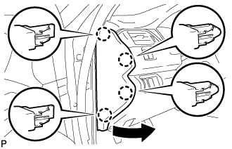 |
Engage the 4 claws to install the instrument side panel LH as shown in the illustration.
| 7. INSTALL FRONT DOOR OPENING TRIM WEATHERSTRIP LH |
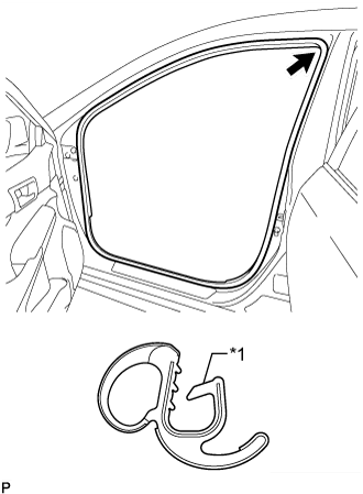 |
Align the alignment mark (Yellow) on the weatherstrip with the protruding portion on the body indicated by the arrow in the illustration, and install the front door opening trim weatherstrip LH.
| *1 | Alignment Mark (Yellow) |
| 8. INSTALL COWL SIDE TRIM SUB-ASSEMBLY LH |
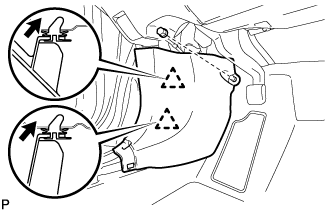 |
Insert the 2 clips in the direction indicated by the arrows shown in the illustration to engage them.
Install the cowl side trim sub-assembly LH with the clip.
| 9. INSTALL FRONT DOOR SCUFF PLATE LH |
Engage the 10 claws to install the front door scuff plate LH.
| 10. INSTALL FRONT PANEL GARNISH LH |
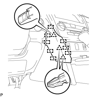 |
Engage the 3 clips and 8 guides to install the front panel garnish LH.
| 11. CONNECT CABLE TO NEGATIVE AUXILIARY BATTERY TERMINAL |
| 12. INSTALL LUGGAGE TRIM SERVICE HOLE COVER |
Engage the claw to connect the luggage trim service hole cover.