 |
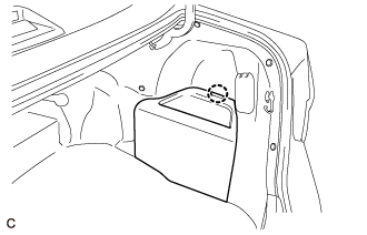
Disengage the claw to remove the luggage trim service hole cover.
INTEGRATION RELAY > REMOVAL |
| 1. PRECAUTION |
| 2. REMOVE LUGGAGE TRIM SERVICE HOLE COVER |
|
Disengage the claw to remove the luggage trim service hole cover.
| 3. DISCONNECT CABLE FROM NEGATIVE AUXILIARY BATTERY TERMINAL |
| 4. REMOVE NO. 1 RELAY BLOCK COVER |
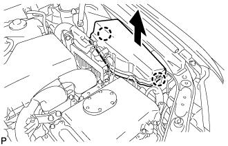 |
Disengage the 2 claws and remove the No. 1 relay block cover as shown in the illustration.
| 5. REMOVE ENGINE ROOM JUNCTION BLOCK ASSEMBLY |
Disengage the 2 claws as shown in the illustration.
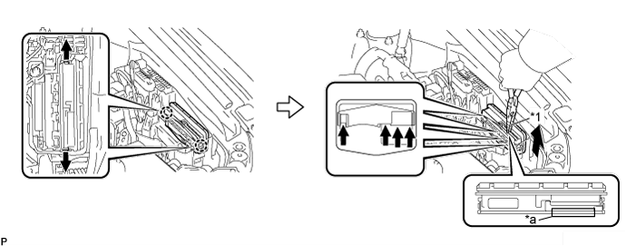
| *1 | Protective Tape | - | - |
| *a | Pulled Position | - | - |
Using pliers, pull up the engine room junction block assembly at the position indicated in the illustration and disconnect the 4 connectors from the engine room relay block assembly.
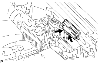 |
Disconnect the 2 connectors and remove the engine room junction block assembly.