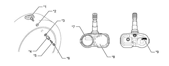
Warning Function
When any of the following conditions are met, the tire pressure warning system illuminates the tire pressure warning light to warn the driver.
Warning Condition - When the tire pressure decreases to approximately 80% or less of the default tire pressure set during system initialization.
- When the tire pressure decreases rapidly (approximately 20 kPa or more over a period of several minutes) and drops below approximately 80% or less of the tire pressure when warm.
- HINT:
- When driving for a certain period of time after the system has been initialized, the system corrects the tire pressure set during initialization according to the vehicle driving conditions and sets the tire pressure when warm.
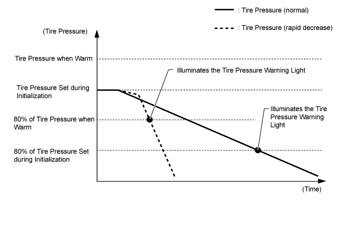
- When the tire pressure decreases to approximately 80% or less of the default tire pressure set during system initialization.
The tire pressure warning system has 2 warning methods which are used depending on the condition detected.
The table below shows the warning methods for the tire pressure warning light in the combination meter assembly:
Detection Condition Tire Pressure Warning Light The tire pressure warning system has detected that the tire pressure has become lower than the warning threshold. Illuminates*1 The tire pressure warning system has detected a malfunction in the system. Illuminates after blinking for 1 minute*2 - *1: If the tire pressure warning light illuminates, adjust the tire pressure.
- *2: If the tire pressure warning light stays on after blinking for 1 minute, the system is malfunctioning and must be repaired in order to turn off the light. For details, refer to the Repair Manual.
- *1: If the tire pressure warning light illuminates, adjust the tire pressure.
Initial Check Function
After the ignition switch is turned to ON, the tire pressure warning ECU and receiver illuminates the tire pressure warning light for 3 seconds to check the warning light circuit.
Initialization Function
The warning threshold is calculated from the tire inflation pressure valve at the time of initialization and memorized in the tire pressure warning ECU and receiver. Therefore, the tire pressure warning ECU and receiver should be initialized after:
- The recommended tire inflation pressure changes due to changes in vehicle weight, speed conditions or tire size.
- Tire pressure warning ECU and receiver or the tire pressure warning valve and transmitter are replaced.
- The tires are rotated on a vehicle with different recommended tire inflation pressures for the front and rear tires.
- The tire pressure is adjusted.
- The recommended tire inflation pressure changes due to changes in vehicle weight, speed conditions or tire size.