 |
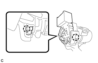
Engage the 2 claws to install the ignition or starter switch assembly to the steering column upper bracket assembly.
STEERING COLUMN ASSEMBLY > REASSEMBLY |
| 1. INSTALL IGNITION OR STARTER SWITCH ASSEMBLY (w/o Smart Entry and Start System) |
|
Engage the 2 claws to install the ignition or starter switch assembly to the steering column upper bracket assembly.
| 2. INSTALL IGNITION SWITCH LOCK CYLINDER ASSEMBLY (w/o Smart Entry and Start System) |
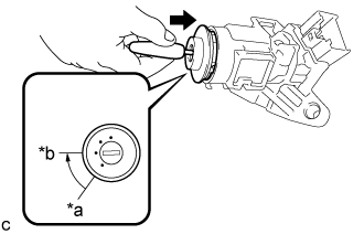 |
Make sure that the ignition switch lock cylinder assembly is in the ACC position.
| *a | LOCK |
| *b | ACC |
Install the ignition switch lock cylinder assembly to the steering column upper bracket assembly.
Make sure that the ignition switch lock cylinder assembly is securely installed.
| 3. INSTALL KEY INTERLOCK SOLENOID (w/o Smart Entry and Start System) |
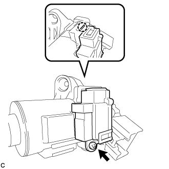 |
Engage the claw to install the key interlock solenoid to the steering column upper bracket assembly.
Install the screw.
| 4. INSTALL UNLOCK WARNING SWITCH ASSEMBLY (w/o Smart Entry and Start System) |
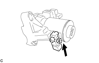 |
Slide the unlock warning switch assembly and engage the 2 claws to install the unlock warning switch assembly to the steering column upper bracket assembly as shown in the illustration.
| 5. INSTALL TRANSPONDER KEY COIL (w/o Smart Entry and Start System) |
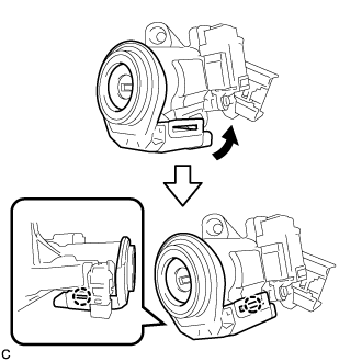 |
Align the transponder key coil with the steering column upper bracket assembly. Tilt the transponder key coil slightly and slide it into position.
Push the transponder key coil, and engage the 2 claws to install the transponder key coil to the steering column upper bracket assembly.
| 6. INSPECT STEERING LOCK OPERATION (w/o Smart Entry and Start System) |
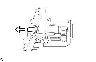 |
Check that the steering lock mechanism is activated when the key is removed.
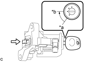 |
Check that the steering lock mechanism is deactivated when the key is inserted and turned to the ACC position.
| *a | LOCK |
| *b | ACC |
| 7. INSTALL POWER STEERING ECU WITH MOTOR ASSEMBLY (for Manual Tilt and Manual Telescopic Steering Column) |
Install a new electric power steering motor shaft damper to the electric power steering column sub-assembly.
Install a new electric power steering motor shaft spacer to the electric power steering column sub-assembly.
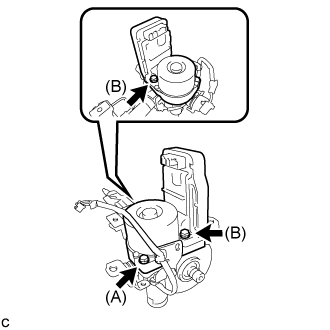 |
Temporarily install the power steering ECU with motor assembly to the electric power steering column sub-assembly with 3 bolts.
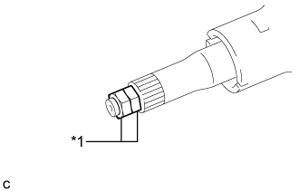 |
Install the 2 service nuts to the steering main shaft.
| *1 | Service Nut |
Simultaneously rotate the service nut that was installed first counterclockwise and rotate the service nut that was installed second clockwise to lock them.
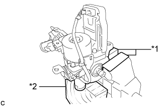 |
Secure the steering column assembly in a vise using aluminum plates as shown in the illustration.
| *1 | Aluminum Plate |
| *2 | Wooden Block |
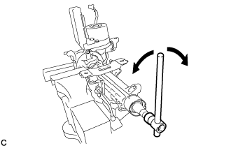 |
Turn the steering main shaft once 180 degrees to the left and then 180 degrees to the right at a speed of 60 rpm, and repeat 2 to 3 times to adjust the axis of the power steering ECU with motor assembly.
Tighten the 3 bolts.
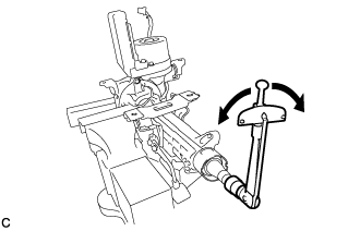 |
Measure the turning torque of the steering main shaft.
Remove the 2 service nuts from the steering main shaft.
Connect the connector to the power steering ECU with motor assembly.
| 8. INSTALL ECU WIRE SUB-ASSEMBLY (for Manual Tilt and Manual Telescopic Steering Column) |
Engage the 2 wire harness clamps to install the ECU wire sub-assembly.
Connect the 2 connectors to the power steering ECU with motor assembly.
| 9. INSTALL POWER STEERING ECU WITH MOTOR ASSEMBLY (for Power Tilt and Power Telescopic Steering Column) |
Install a new electric power steering motor shaft damper to the electric power steering column sub-assembly.
Install a new electric power steering motor shaft spacer to the electric power steering column sub-assembly.
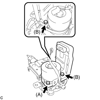 |
Temporarily install the power steering ECU with motor assembly to the electric power steering column sub-assembly with 3 bolts.
|
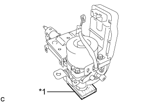
Install the 2 service nuts to the steering main shaft.
| *1 | Service Nut |
Simultaneously rotate the service nut that was installed first counterclockwise and rotate the service nut that was installed second clockwise to lock them.
 |
Securely set the steering column assembly on a wooden block or similar item.
| *1 | Wooden Block |
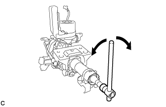 |
Turn the steering main shaft once 180 degrees to the left and then 180 degrees to the right at a speed of 60 rpm, and repeat 2 to 3 times to adjust the axis of the power steering ECU with motor assembly.
Tighten the 3 bolts.
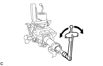 |
Measure the turning torque of the steering main shaft.
Remove the 2 service nuts from the steering main shaft.
Connect the connector to the power steering ECU with motor assembly.
| 10. INSTALL ECU WIRE SUB-ASSEMBLY (for Power Tilt and Power Telescopic Steering Column) |
Engage the 2 wire harness clamps to install the ECU wire sub-assembly.
Connect the 2 connectors to the power steering ECU with motor assembly.
| 11. INSTALL POWER STEERING ECU PROTECTOR |
Install a new power steering ECU protector to the power steering ECU with motor assembly.
| 12. INSTALL MULTIPLEX TILT AND TELESCOPIC ECU (for Power Tilt and Power Telescopic Steering Column) |
Engage the claw to install the multiplex tilt and telescopic ECU to the electric power steering column sub-assembly.
| 13. INSTALL STEERING COLUMN UPPER WITH SWITCH BRACKET ASSEMBLY (w/o Smart Entry and Start System) |
Secure the steering column assembly in a vise.
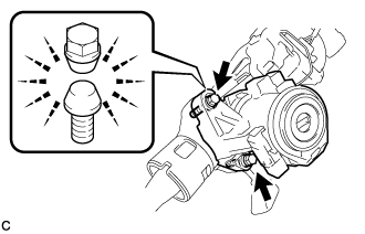 |
Temporarily install the steering column upper with switch bracket assembly to the steering column assembly with 2 new tapered-head bolts.
Tighten the 2 tapered-head bolts until the bolt heads break off.
| 14. INSTALL STEERING LOCK ACTUATOR ASSEMBLY (w/ Smart Entry and Start System) |
for Manual Tilt and Manual Telescopic Steering Column
Secure the steering column assembly in a vise.
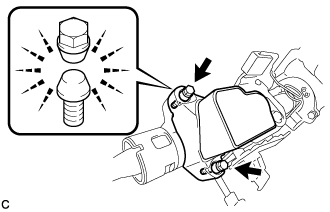 |
Temporarily install the steering lock actuator assembly to the steering column assembly with 2 new tapered-head bolts.
Tighten the 2 tapered-head bolts until the bolt heads break off.
for Power Tilt and Power Telescopic Steering Column
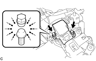 |
Temporarily install the steering lock actuator assembly to the steering column assembly with the 2 new tapered-head bolts.
Tighten the 2 tapered-head bolts until the bolt heads break off.