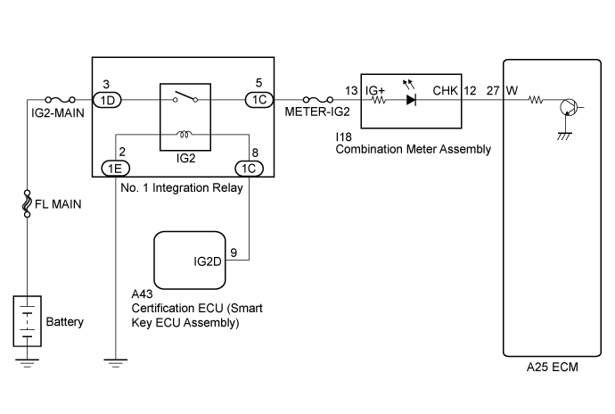
SFI SYSTEM > MIL Circuit |
| 1.CHECK THAT MIL IS ILLUMINATED |
Perform troubleshooting in accordance with the table below.
| Result | Proceed to |
| MIL remains ON | A |
| MIL does not illuminate | B |
|
| ||||
| A | |
 |
| 2.CHECK WHETHER DTC OUTPUT RECURS |
Connect the intelligent tester to the DLC3.
Turn the engine switch on (IG).
Turn the tester on.
Enter the following menus: Powertrain / Engine / DTC.
Check if any DTCs have been detected. Note down any DTCs.
| Result | Proceed to |
| DTC is not output | A |
| Any DTCs is output | B |
|
| ||||
| A | |
|
| 3.CHECK HARNESS AND CONNECTOR (CHECK FOR SHORT IN WIRE HARNESS) |
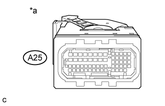 |
Disconnect the ECM connector.
Turn the engine switch on (IG).
Check that the MIL is not illuminated.
| *a | Front view of wire harness connector (to ECM) |
|
| ||||
| OK | ||
 | ||
| ||
| 4.CHECK HARNESS AND CONNECTOR (COMBINATION METER ASSEMBLY - ECM) |
Disconnect the combination meter assembly connector.
Disconnect the ECM connector.
Measure the resistance according to the value(s) in the table below.
| Tester Connection | Condition | Specified Condition |
| I18-12 (CHK) or A25-27 (W) - Body ground | Always | 10 kΩ or higher |
|
| ||||
| OK | ||
| ||
| ||
| 5.CHECK THAT MIL IS ILLUMINATED |
Check if the MIL is illuminated when the engine switch is turned on (IG).
|
| ||||
| OK | ||
| ||
| ||
| 6.CHECK THAT ENGINE STARTS |
Start the engine.
| Result | Proceed to |
| Engine starts | A |
| Engine does not start* | B |
|
| ||||
| A | |
|
| 7.CHECK HARNESS AND CONNECTOR (COMBINATION METER ASSEMBLY - ECM) |
Disconnect the combination meter assembly connector.
Disconnect the ECM connector.
Measure the resistance according to the value(s) in the table below.
| Tester Connection | Condition | Specified Condition |
| I18-12 (CHK) - A25-27 (W) | Always | Below 1 Ω |
|
| ||||
| OK | ||
| ||
| ||

