 |
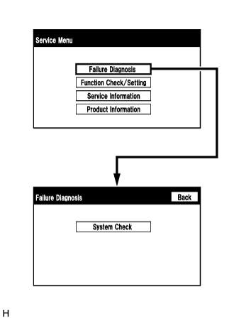
The "Failure Diagnosis" screen will be displayed by selecting the "Failure Diagnosis" switch on the "Service Menu" screen.
AUDIO AND VISUAL SYSTEM (for Radio and Display Type) > DTC CHECK / CLEAR |
| CHECK DTC (CHECK USING GTS) |
Connect the GTS to the DLC3.
Turn the ignition switch to ON.
Turn the GTS on.
Enter the following menus: Body Electrical / Navigation System / Trouble Codes.
Check for DTCs, and then write them down.
Check the details of the DTC(s) (Click here).
| System | Proceed to |
| Rear View Monitor System |
Click here
|
| CLEAR DTC (CLEAR USING GTS) |
Connect the GTS to the DLC3.
Turn the ignition switch to ON.
Turn the GTS on.
Enter the following menus: Body Electrical / Navigation System / Trouble Codes.
Clear the DTCs.
| START DIAGNOSTIC MODE |
Turn the ignition switch to ON.
While pressing and holding the "AUDIO" switch, operate the light control switch: Off → Tail → Off → Tail → Off → Tail → Off.
Diagnostic mode starts and the "Service Menu" screen will be displayed. Service inspection starts automatically and the result will be displayed.
| FAILURE DIAGNOSIS |
|
The "Failure Diagnosis" screen will be displayed by selecting the "Failure Diagnosis" switch on the "Service Menu" screen.
| SYSTEM CHECK |
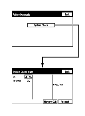 |
The "System Check Mode" screen will be displayed by selecting the "System Check" switch on the "Failure Diagnosis" screen.
| CHECK DTC (CHECK USING SYSTEM CHECK MODE SCREEN) |
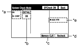 |
System check mode screen description
| Display | Content |
| *a: Device name list No. 1 |
|
| *b: Check result | Result codes for all devices are displayed. |
| *c: Memory clear |
|
| *d: Recheck |
|
| *e: Device name list No. 2 |
|
| Name | Component | Connection Method |
| DA | Radio and display receiver assembly | - |
| Rr-CONT* | Cooler Control Switch Assembly | AVC-LAN communication line |
| Result | Meaning | Action |
| OK | The device does not respond with a DTC. | - |
| DETAIL | The device responds with a DTC. | Read DTCs on the "Unit Check Mode" screen. |
| NCON* | The device was previously present, but does not respond in diagnostic mode. | - Check the power supply circuit of the device. - Check the communication line of the device. |
| NRES* | The device responds in diagnostic mode, but gives no DTC information. | - Check the power supply circuit of the device. - Check the communication line of the device. |
| Name | Component | Connection Method |
| AUX/VTR | No. 1 stereo jack adapter assembly | Vehicle wire harness |
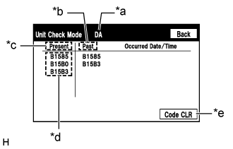 |
Unit check mode screen description
| Display | Content |
| *a: Device name | Target device |
| *b: History DTC | Diagnostic memory results and stored DTCs are displayed. |
| *c: Current DTC | DTCs output in the service check are displayed. |
| *d: DTC | DTC (Diagnostic Trouble Code) |
| *e: Diagnosis clear | Selecting "Code CLR" for 3 seconds clears the diagnostic memory data of the target device (both diagnostic system check result and the displayed data are cleared). |
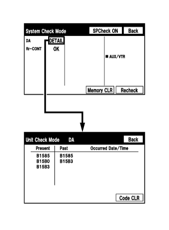 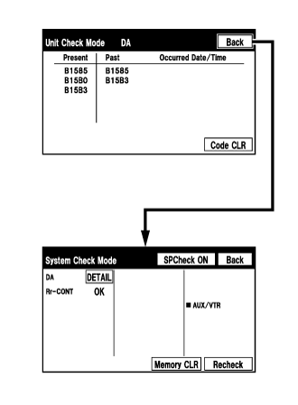 |
Read the system check result.
If the check result is "DETAIL", select the displayed check result to view the results on the "Unit Check Mode" screen and record them.
Check the details of the DTC(s) (Click here).
| System | Proceed to |
| Rear View Monitor System |
Click here
|
| DTC CLEAR/RECHECK (CLEAR USING SYSTEM CHECK MODE SCREEN) |
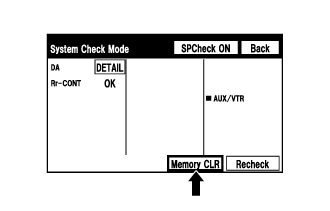 |
Clear DTCs
Select "Memory CLR" for 3 seconds.
Confirm that the check results are cleared.
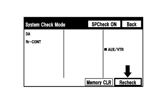 |
Recheck
Select "Recheck".
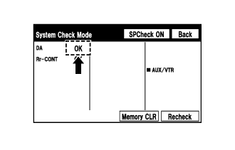 |
Confirm that all diagnostic codes are "OK" when the check results are displayed. If a result other than "OK" is displayed, perform troubleshooting again.
| FINISH DIAGNOSTIC MODE |
Turn the ignition switch off.