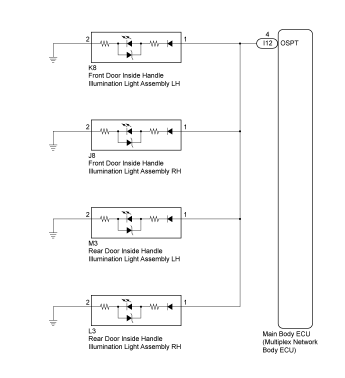
LIGHTING SYSTEM > Inside Handle Illumination Light Circuit |
| 1.PERFORM ACTIVE TEST USING INTELLIGENT TESTER |
Connect the intelligent tester to the DLC3.
Turn the ignition switch to ON.
Turn the intelligent tester on.
Enter the following menus: Body / Main Body / Active Test.
Check that the inside handle illumination lights come on.
| Tester Display | Test Part | Control Range | Diagnostic Note |
| Inside Handle Illumination | Inside handle illumination lights | ON/OFF | Ignition switch is turned off just before performing the Active Test. |
|
| ||||
| OK | ||
 | ||
| ||
| 2.CHECK HARNESS AND CONNECTOR (INSIDE HANDLE ILLUMINATION LIGHT ASSEMBLY - MAIN BODY ECU (MULTIPLEX NETWORK BODY ECU)) |
Disconnect the I12 main body ECU (multiplex network body ECU) connector.
Disconnect the K8 front door inside handle illumination light assembly LH connector.
Disconnect the J8 front door inside handle illumination light assembly RH connector.
Disconnect the M3 rear door inside handle illumination light assembly LH connector.
Disconnect the L3 rear door inside handle illumination light assembly RH connector.
Measure the resistance according to the value(s) in the table below.
| Tester Connection | Condition | Specified Condition |
| I12-4 (OSPT) - K8-1 | Always | Below 1 Ω |
| I12-4 (OSPT) - J8-1 | Always | Below 1 Ω |
| I12-4 (OSPT) - M3-1 | Always | Below 1 Ω |
| I12-4 (OSPT) - L3-1 | Always | Below 1 Ω |
| I12-4 (OSPT) - Body ground | Always | 10 kΩ or higher |
|
| ||||
| OK | ||
| ||
| ||

