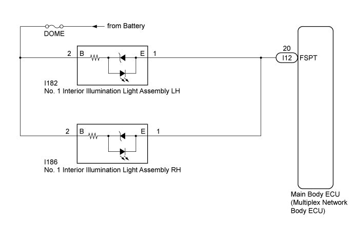
LIGHTING SYSTEM > Footwell Light Circuit |
| 1.PERFORM ACTIVE TEST USING INTELLIGENT TESTER |
Connect the intelligent tester to the DLC3.
Turn the ignition switch to ON.
Turn the intelligent tester on.
Enter the following menus: Body Electrical / Main Body / Active Test.
Perform the Active Test according to the display on the intelligent tester.
| Tester Display | Test Part | Control Range | Diagnostic Note |
| Fr Foot Light | Footwell lights | ON/OFF | Turn off the ignition switch just before performing the Active Test. |
|
| ||||
| OK | ||
 | ||
| ||
| 2.CHECK HARNESS AND CONNECTOR (DOME FUSE - NO. 1 INTERIOR ILLUMINATION LIGHT ASSEMBLY) |
Disconnect the I182 No. 1 interior illumination light assembly LH connector.
Disconnect the I186 No. 1 interior illumination light assembly RH connector.
Measure the voltage according to the value(s) in the table below.
| Tester Connection | Condition | Specified Condition |
| I182-2 (B) - Body ground | Always | 11 to 14 V |
| I186-2 (B) - Body ground | Always | 11 to 14 V |
|
| ||||
| OK | |
 |
| 3.CHECK HARNESS AND CONNECTOR (NO. 1 INTERIOR ILLUMINATION LIGHT ASSEMBLY - MAIN BODY ECU (MULTIPLEX NETWORK BODY ECU)) |
Disconnect the I12 main body ECU (multiplex network body ECU) connector.
Measure the resistance according to the value(s) in the table below.
| Tester Connection | Condition | Specified Condition |
| I182-1 (E) - I12-20 (FSPT) | Always | Below 1 Ω |
| I186-1 (E) - I12-20 (FSPT) | Always | Below 1 Ω |
| I182-1 (E) - Body ground | Always | 10 kΩ or higher |
| I186-1 (E) - Body ground | Always | 10 kΩ or higher |
|
| ||||
| OK | ||
| ||
| ||

