AUTOMATIC TRANSAXLE UNIT > INSPECTION |
| 1. INSPECT TRANSMISSION OIL CLEANER MAGNET |
![]() |
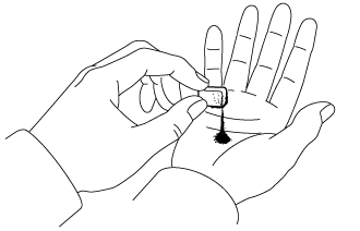
Use the removed transmission oil cleaner magnets to collect any steel chips. Examine the chips and particles in the automatic transaxle oil pan sub-assembly and on the transmission oil cleaner magnets to determine what type of wear has occurred in the automatic transaxle assembly:
| 2. INSPECT INPUT SHAFT SUB-ASSEMBLY END PLAY |
![]() |
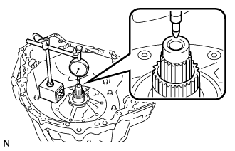
Using a dial indicator, measure the input shaft sub-assembly end play.
| 3. INSPECT NO. 2 CLUTCH DISC |
![]() |
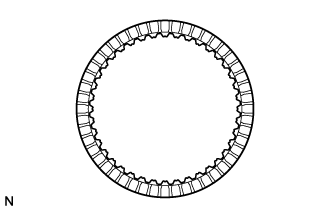
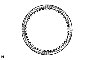
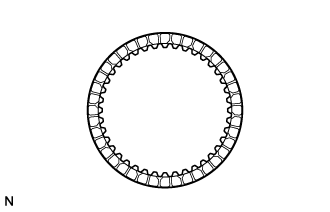
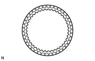
Check if the contact surfaces of the No. 2 clutch discs, No. 2 clutch plates and No. 2 clutch flange are worn or burnt.
| 4. INSPECT PLANETARY SUN GEAR SUB-ASSEMBLY |
![]() |
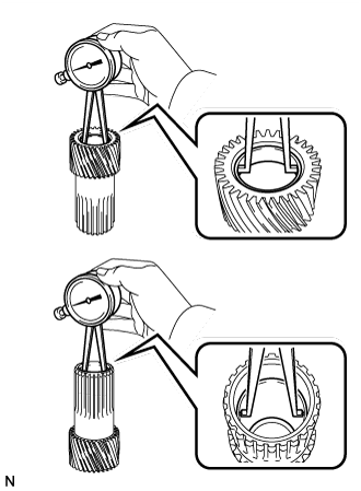
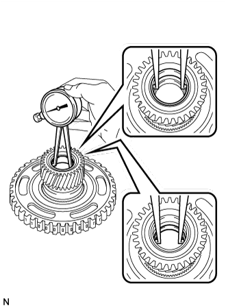
Using a caliper gauge, measure the inside diameter of the bushings of the planetary sun gear sub-assembly.
| 5. INSPECT NO. 1 CLUTCH DISC |
![]() |
Check if the contact surfaces of the No. 1 clutch discs, No. 1 clutch plates and No. 1 clutch flange are worn or burnt.
| 6. INSPECT NO. 3 BRAKE DISC |
![]() |
Check if the contact surfaces of the No. 3 brake discs, No. 3 brake plates and No. 3 brake flanges are worn or burnt.
| 7. INSPECT UNDERDRIVE PLANETARY GEAR ASSEMBLY |
![]() |
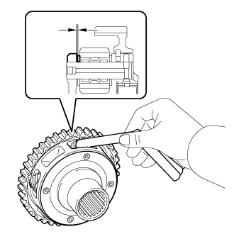
Using a feeler gauge, measure the clearance between the underdrive planetary gear assembly and pinion gear at 4 points.
| 8. INSPECT REAR PLANETARY SUN GEAR ASSEMBLY |
![]() |
Using a caliper gauge, measure the inside diameter of the bushings of the rear planetary sun gear assembly.
| 9. INSPECT NO. 1 BRAKE DISC |
![]() |
Check if the contact surfaces of the No. 1 brake discs, No. 1 brake plates and No. 1 brake flange are worn or burnt.
| 10. INSPECT 2ND BRAKE PISTON RETURN SPRING SUB-ASSEMBLY |
![]() |
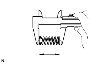
Using a vernier caliper, measure the free length of the 3 2nd brake piston return spring sub-assemblies including the spring seats.
| 11. INSPECT ONE-WAY CLUTCH ASSEMBLY |
![]() |
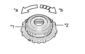
Temporarily install the one-way clutch assembly to the planetary ring gear.
| *1 | Planetary Ring Gear |
| *2 | One-way Clutch Assembly |
| *a | Free |
| *b | Lock |
Make sure that the one-way clutch assembly turns freely counterclockwise and locks when turned clockwise.
If the one-way clutch assembly does not operate normally, replace it.
| 12. INSPECT FRONT PLANETARY GEAR ASSEMBLY |
![]() |
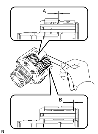
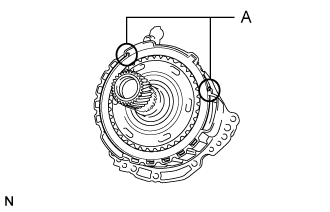
Using a feeler gauge, measure the clearance between the front planetary gear case and each pinion gear at points (A) and (B).
| 13. INSPECT NO. 2 BRAKE DISC |
![]() |
Check if the contact surfaces of the No. 2 brake discs, No. 2 brake plates and No. 2 brake flange are worn or burnt.
| 14. INSPECT 1ST AND REVERSE BRAKE RETURN SPRING SUB-ASSEMBLY |
![]() |
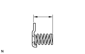
Using a vernier caliper, measure the free length of the 1st and reverse brake return spring sub-assembly including the spring seat.
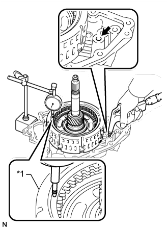
| 15. INSPECT CLEARANCE OF NO. 2 BRAKE |
![]() |
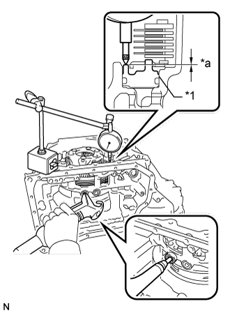
Apply compressed air to the oil pressure supply hole shown in the illustration, and check the operation of the No. 2 brake piston.
| *1 | No. 2 Brake Piston |
| *a | Clearance |
Set a dial indicator as shown in the illustration.
Using a dial indicator, measure the clearance of the No. 2 brake while applying compressed air (200 kPa, 2.0 kgf/cm2, 29 psi).
| Mark | Thickness |
| 40 | 4.0 (0.157) |
| 41 | 4.1 (0.161) |
| 42 | 4.2 (0.165) |
| 43 | 4.3 (0.169) |
| 44 | 4.4 (0.173) |
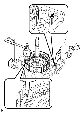
| 16. INSPECT CLEARANCE OF NO. 1 BRAKE |
![]() |
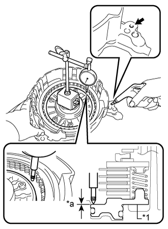
Apply compressed air to the oil pressure supply hole shown in the illustration, and check the operation of the No. 1 brake piston.
| *1 | No. 1 Brake Piston |
| *a | Clearance |
Set a dial indicator as shown in the illustration.
Using a dial indicator, measure the clearance of the No. 1 brake while applying compressed air (200 kPa, 2.0 kgf/cm2, 29 psi).
| Mark | Thickness |
| 30 | 3.0 (0.118) |
| 31 | 3.1 (0.122) |
| 32 | 3.2 (0.126) |
| 33 | 3.3 (0.130) |
| 34 | 3.4 (0.134) |
| 35 | 3.5 (0.138) |
| 36 | 3.6 (0.142) |
| 17. INSPECT CLEARANCE OF NO. 3 BRAKE |
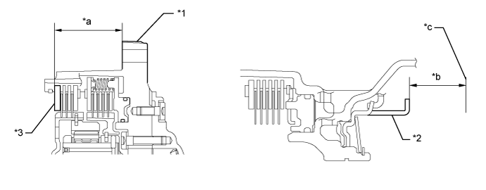
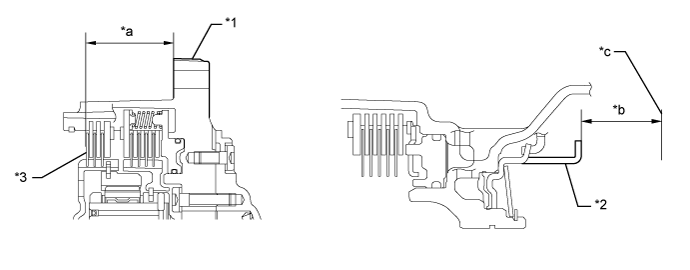
Using a vernier caliper and a straightedge, measure the distance shown in the illustration (Dimension (A)) while a load of 500 N (51 kgf, 112.4 lbf) is being applied to the flange.

| *1 | Front Oil Pump Assembly | *2 | No. 3 Brake Piston |
| *3 | No. 3 Brake Flange | - | - |
| *a | Dimension (A) | *b | Dimension (B) |
| *c | Contact Surface of Front Oil Pump Assembly | - | - |
Using a vernier caliper and a straightedge, measure the distance shown in the illustration (Dimension (B)).
Calculate the clearance value using the following formula:
Clearance = Dimension (B) - Dimension (A)
Adjust clearance of No. 3 brake piston:
![]() |
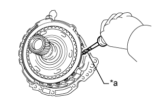
Using a screwdriver with its tip wrapped with protective tape, remove the snap ring from the front oil pump assembly.
| *a | Protective Tape |
![]() |
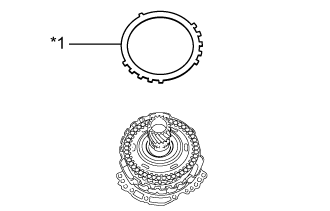
Remove the No. 3 brake flange from the front oil pump assembly.
| *1 | No. 3 Brake Flange |
Using a vernier caliper and a straightedge, measure the distance shown in the illustration (Dimension (A)) while a load of 500 N (51 kgf, 112.4 lbf) is being applied to the No. 3 brake disc.

| *1 | Front Oil Pump Assembly | *2 | No. 3 Brake Piston |
| *3 | No. 3 Brake Disc | - | - |
| *a | Dimension (A) | *b | Dimension (B) |
| *c | Contact Surface of Front Oil Pump Assembly | - | - |
Using a vernier caliper and a straightedge, measure the distance shown in the illustration (Dimension (B)).
Calculate the thickness of the replacement No. 3 brake flange using the following formula:
| Mark | Thickness |
| 37 | 3.7 (0.146) |
| 38 | 3.8 (0.150) |
| 39 | 3.9 (0.154) |
| 40 | 4.0 (0.157) |
| 41 | 4.1 (0.161) |
| 42 | 4.2 (0.165) |
| 43 | 4.3 (0.169) |
| 44 | 4.4 (0.173) |
| 45 | 4.5 (0.177) |
![]() |
Install the No. 3 brake flange to the front oil pump assembly.
| *1 | No. 3 Brake Flange |
![]() |
Using a screwdriver with its tip wrapped with protective tape, install the snap ring to the front oil pump assembly.
| 18. INSPECT CLEARANCE OF NO. 1 CLUTCH DISC |
Install the direct multiple disc clutch assembly to the rear transaxle cover sub-assembly.
![]() |
Using a dial indicator, measure the No. 1 clutch pack clearance while applying and releasing compressed air (200 kPa, 2.0 kgf/cm2, 29 psi).
| Mark | Thickness |
| 30 | 3.0 (0.118) |
| 31 | 3.1 (0.122) |
| 32 | 3.2 (0.126) |
| 33 | 3.3 (0.130) |
| 34 | 3.4 (0.134) |
| 35 | 3.5 (0.138) |
| 19. INSPECT CLEARANCE OF NO. 2 CLUTCH DISC |
Install the direct multiple disc clutch assembly to the rear transaxle cover sub-assembly.
![]() |
Using a dial indicator, measure the No. 2 clutch pack clearance while applying and releasing compressed air (200 kPa, 2.0 kgf/cm2, 29 psi).
| *1 | No. 2 Direct Clutch Piston |
| Mark | Thickness |
| 30 | 3.0 (0.118) |
| 31 | 3.1 (0.122) |
| 32 | 3.2 (0.126) |
| 33 | 3.3 (0.130) |
| 34 | 3.4 (0.134) |
| 35 | 3.5 (0.138) |