AUTOMATIC TRANSAXLE UNIT > REASSEMBLY |
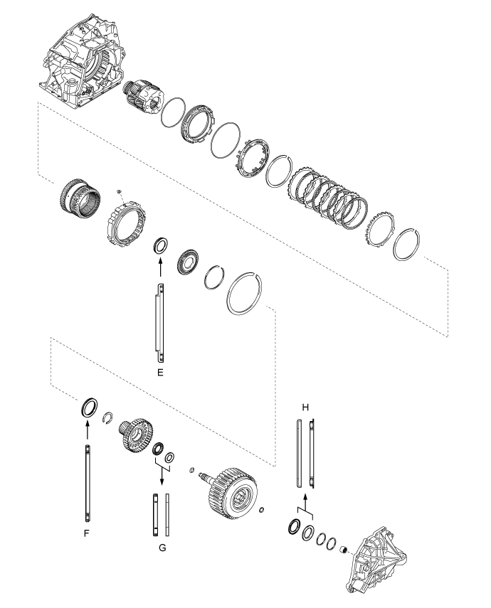
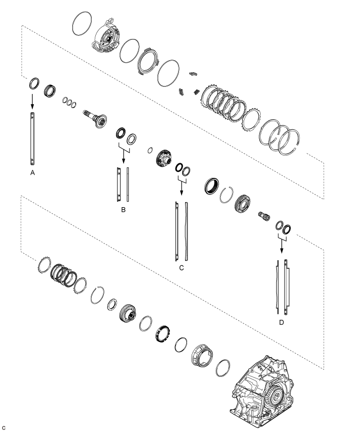
| Mark | Front Race Diameter Inside / Outside (mm (in.)) | Thrust Bearing Diameter Inside / Outside (mm (in.)) | Rear Race Diameter Inside / Outside (mm (in.)) |
| A | - | 57.7 (2.27) / 75.2 (2.96) | - |
| B | - | 29.1 (1.15) / 48.6 (1.91) | 30.7 (1.21) / 48.3 (1.90) |
| C | - | 62.6 (2.46) / 82.4 (3.24) | 65.9 (2.59) / 82.3 (3.24) |
| D | 59.4 (2.34) / 76 (2.99) | 53.46 (2.10) / 79 (3.11) | - |
| E | - | 56.1 (2.21) / 81.1 (3.19) | - |
| F | - | 61.2 (2.41) / 79 (3.11) | - |
| G | - | 28 (1.10) / 47.1 (1.85) | 26.1 (1.03) / 44 (1.73) |
| H | 52.2 (2.06) / 70.4 (2.77) | 48.9 (1.93) / 72.0 (2.83) | - |
| 1. INSTALL COUNTER DRIVE GEAR BEARING |
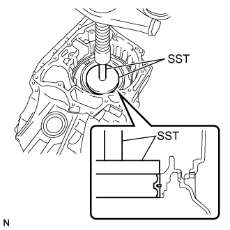 |
Using SST and a press, install a new counter drive gear bearing (outer race) and snap ring to the transaxle case sub-assembly.
| 2. INSTALL FRONT DIFFERENTIAL CASE REAR TAPERED ROLLER BEARING (OUTER RACE) |
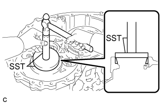 |
Using SST and a hammer, install a new front differential case rear tapered roller bearing (outer race) to the transaxle case sub-assembly.
| 3. INSTALL FRONT DIFFERENTIAL CASE FRONT TAPERED ROLLER BEARING (OUTER RACE) |
Install the shim to the transaxle housing.
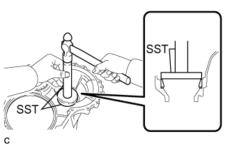 |
Using SST and a hammer, install a new front differential case front tapered roller bearing (outer race) to the transaxle housing.
| 4. INSTALL FRONT DIFFERENTIAL CASE REAR TAPERED ROLLER BEARING (INNER RACE) |
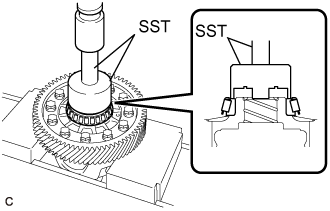 |
Using SST and a press, install a new front differential case rear tapered roller bearing (inner race) to the front differential case.
| 5. INSTALL FRONT DIFFERENTIAL CASE FRONT TAPERED ROLLER BEARING (INNER RACE) |
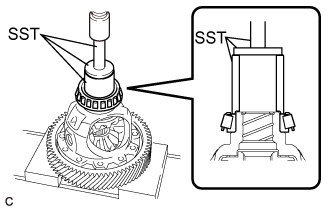 |
Using SST and a press, install a new front differential case front tapered roller bearing (inner race) to the front differential case.
| 6. ADJUST DIFFERENTIAL SIDE BEARING PRELOAD |
Remove any remaining seal packing from the contact surfaces of the transaxle housing and transaxle case sub-assembly.
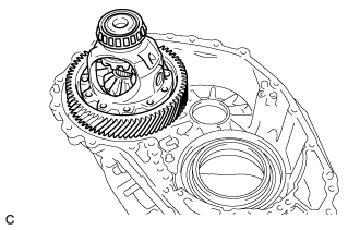 |
Install the front differential case to the transaxle case sub-assembly.
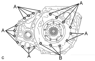 |
Install the transaxle housing to the transaxle case sub-assembly with the 20 bolts.
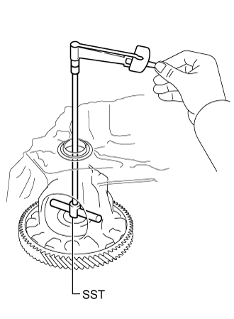 |
Using SST, turn the front differential case right and left 2 or 3 times to settle the bearings.
Using SST and a torque wrench, measure the turning torque of the differential side bearings while rotating SST at 10 rpm.
| Part No. | Thickness (mm (in.)) |
| 90564-69001 | 2.000 (0.0787) |
| 90564-69002 | 2.025 (0.0797) |
| 90564-69003 | 2.050 (0.0807) |
| 90564-69004 | 2.075 (0.0817) |
| 90564-69005 | 2.100 (0.0827) |
| 90564-69006 | 2.125 (0.0837) |
| 90564-69007 | 2.150 (0.0846) |
| 90564-69008 | 2.175 (0.0856) |
| 90564-69009 | 2.200 (0.0866) |
| 90564-69010 | 2.225 (0.0876) |
| 90564-69011 | 2.250 (0.0886) |
| 90564-69012 | 2.275 (0.0896) |
| 90564-69013 | 2.300 (0.0906) |
| 90564-69014 | 2.325 (0.0915) |
| 90564-69015 | 2.350 (0.0925) |
| 90564-69016 | 2.375 (0.0935) |
| 90564-69017 | 2.400 (0.0945) |
| 90564-69020 | 2.425 (0.0955) |
| 90564-69021 | 2.450 (0.0965) |
| 90564-69022 | 2.475 (0.0974) |
| 90564-69023 | 2.500 (0.0984) |
| 90564-69024 | 2.525 (0.0994) |
| 90564-69025 | 2.550 (0.100) |
| 90564-69026 | 2.575 (0.101) |
| 90564-69027 | 2.600 (0.102) |
| 90564-69028 | 2.625 (0.103) |
| 90564-69029 | 2.650 (0.104) |
| 90564-69030 | 2.675 (0.105) |
| 90564-69031 | 2.700 (0.106) |
| 90564-69032 | 2.725 (0.107) |
| 90564-69033 | 2.750 (0.108) |
| 90564-69034 | 2.775 (0.109) |
| 90564-69035 | 2.800 (0.110) |
| 90564-69036 | 2.825 (0.111) |
| 90564-69037 | 2.850 (0.112) |
| 90564-69038 | 2.875 (0.113) |
Remove the 20 bolts and transaxle housing from the transaxle case sub-assembly.
Remove the front differential case from the transaxle case sub-assembly.
| 7. INSTALL DIFFERENTIAL DRIVE PINION TAPERED ROLLER BEARING LH (OUTER RACE) |
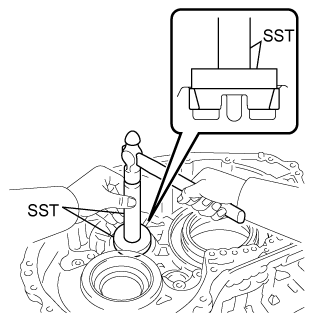 |
Using SST and a hammer, install a new differential drive pinion tapered roller bearing LH (outer race) to the transaxle case sub-assembly.
| 8. INSTALL DIFFERENTIAL DRIVE PINION TAPERED ROLLER BEARING RH (OUTER RACE) |
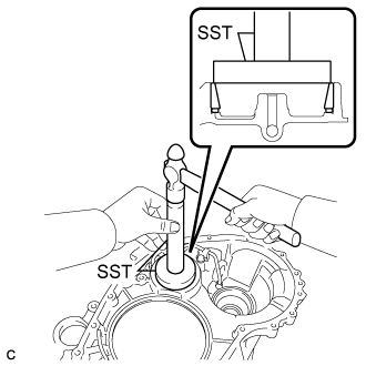 |
Install the shim to the transaxle housing.
Using SST, install a new differential drive pinion tapered roller bearing RH (outer race) to the transaxle housing.
| 9. INSTALL DIFFERENTIAL DRIVE PINION TAPERED ROLLER BEARING LH (INNER RACE) |
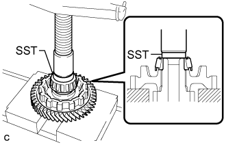 |
Using SST and a press, install a new differential drive pinion tapered roller bearing LH (inner race) to the counter driven gear.
| 10. INSTALL DIFFERENTIAL DRIVE PINION TAPERED ROLLER BEARING RH (INNER RACE) |
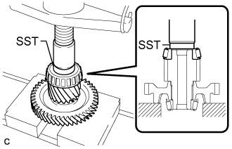 |
Using SST and a press, install a new differential drive pinion tapered roller bearing RH (inner race) to the counter driven gear.
| 11. ADJUST COUNTER DRIVEN GEAR PRELOAD |
Remove any remaining seal packing from the contact surfaces of the transaxle housing and transaxle case sub-assembly.
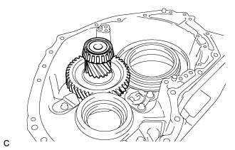 |
Install the counter driven gear to the transaxle case sub-assembly.
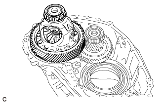 |
Install the front differential case to the transaxle case sub-assembly.
|
Install the transaxle housing to the transaxle case sub-assembly with the 20 bolts.
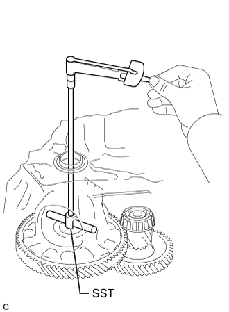 |
Using SST and a torque wrench, measure the turning torque of the counter driven gear while rotating SST at 10 rpm.
| Part No. | Thickness (mm (in.)) |
| 90564-61022 | 2.000 (0.0787) |
| 90564-61023 | 2.025 (0.0797) |
| 90564-61024 | 2.050 (0.0807) |
| 90564-61025 | 2.075 (0.0817) |
| 90564-61026 | 2.100 (0.0827) |
| 90564-61027 | 2.125 (0.0837) |
| 90564-61028 | 2.150 (0.0846) |
| 90564-61029 | 2.175 (0.0856) |
| 90564-61030 | 2.200 (0.0866) |
| 90564-61031 | 2.225 (0.0876) |
| 90564-61032 | 2.250 (0.0886) |
| 90564-61033 | 2.275 (0.0896) |
| 90564-61034 | 2.300 (0.0906) |
| 90564-61035 | 2.325 (0.0915) |
| 90564-61036 | 2.350 (0.0925) |
| 90564-61037 | 2.375 (0.0935) |
| 90564-61038 | 2.400 (0.0945) |
| 90564-61039 | 2.425 (0.0955) |
| 90564-61040 | 2.450 (0.0965) |
| 90564-61041 | 2.475 (0.0974) |
| 90564-61042 | 2.500 (0.0984) |
| 90564-61043 | 2.525 (0.0994) |
| 90564-61044 | 2.550 (0.100) |
| 90564-61045 | 2.575 (0.101) |
| 90564-61046 | 2.600 (0.102) |
| 90564-61047 | 2.625 (0.103) |
| 90564-61048 | 2.650 (0.104) |
| 90564-69049 | 2.675 (0.105) |
| 90564-61050 | 2.700 (0.106) |
| 90564-61051 | 2.725 (0.107) |
| 90564-61052 | 2.750 (0.108) |
| 90564-61053 | 2.775 (0.109) |
| 90564-61054 | 2.800 (0.110) |
| 90564-61055 | 2.825 (0.111) |
| 90564-61056 | 2.850 (0.112) |
| 90564-61057 | 2.875 (0.113) |
| 90564-61058 | 2.900 (0.114) |
| 90564-61059 | 2.925 (0.115) |
| 90564-61060 | 2.950 (0.116) |
| 90564-61061 | 2.975 (0.117) |
| 90564-61062 | 3.000 (0.118) |
Remove the 20 bolts and transaxle housing from the transaxle case sub-assembly.
Remove the front differential case from the transaxle case sub-assembly.
Remove the counter driven gear from the transaxle case sub-assembly.
| 12. INSTALL MANUAL VALVE LEVER SHAFT OIL SEAL |
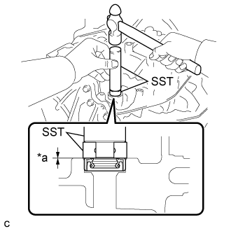 |
Coat the lip of a new manual valve lever shaft oil seal with a small amount of MP grease.
| *a | Depth |
Using SST and a hammer, install the manual valve lever shaft oil seal to the transaxle case sub-assembly.
| 13. INSTALL MANUAL VALVE LEVER SHAFT SUB-ASSEMBLY |
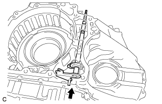 |
Install the manual valve lever shaft sub-assembly to the transaxle case sub-assembly.
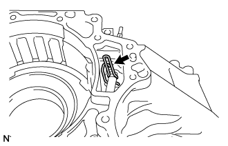 |
Using needle-nose pliers, install the manual valve lever shaft retainer spring to the manual valve lever shaft sub-assembly.
| 14. INSTALL PARKING LOCK ROD SUB-ASSEMBLY |
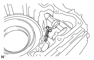 |
Align the protrusions on the parking lock rod sub-assembly with the notches on the manual valve lever shaft sub-assembly and install the parking lock rod sub-assembly.
| 15. INSTALL MANUAL DETENT SPRING SUB-ASSEMBLY |
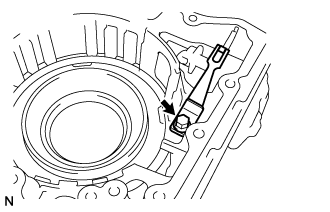 |
Install the manual detent spring sub-assembly and manual detent spring cover to the transaxle case sub-assembly with the bolt.
| 16. INSTALL NO. 3 BRAKE PISTON |
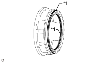 |
Coat 2 new O-rings with ATF and install them to the No. 3 brake piston.
| *1 | O-ring |
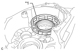 |
Temporarily install the No. 3 brake piston to the transaxle case sub-assembly.
| *1 | No. 3 Brake Piston |
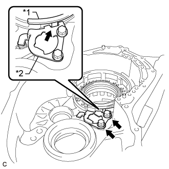 |
Temporarily install the pawl stopper plate to the transaxle case sub-assembly with the 2 bolts.
| *1 | No. 3 Brake Piston |
| *2 | Pawl Stopper Plate |
Press the No. 3 brake piston into the transaxle case sub-assembly.
Remove the 2 bolts and pawl stopper plate from the transaxle case sub-assembly.
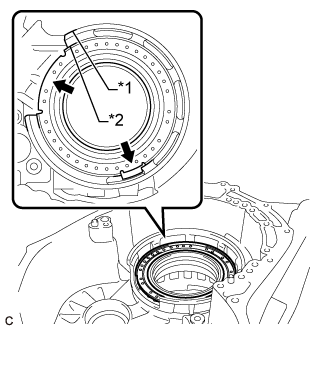 |
Install the No. 3 brake piston return spring sub-assembly to the transaxle case sub-assembly.
| *1 | No. 3 Brake Piston |
| *2 | No. 3 Brake Piston Return Spring Sub-assembly |
Place SST on the No. 3 brake piston return spring sub-assembly and compress the No. 3 brake piston return spring sub-assembly with a press.
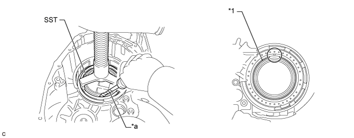
| *1 | Snap Ring | - | - |
| *a | Protective Tape | - | - |
Using a screwdriver with its tip wrapped with protective tape, install the snap ring to the transaxle case sub-assembly as shown in the illustration.
| 17. INSTALL COUNTER DRIVE GEAR |
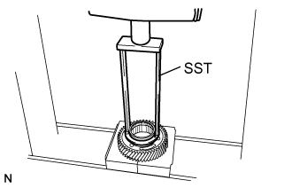 |
Using SST and a press, install a new counter drive gear bearing inner race (front side) to the counter drive gear.
Install 2 new counter drive gear bearings (balls and cage) to the counter drive gear bearing (outer race).
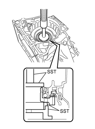 |
Using SST, install the counter drive gear with counter drive gear bearing inner race (front side) and a new counter drive gear bearing inner race (rear side) to the transaxle case sub-assembly.
| 18. INSTALL FRONT PLANETARY GEAR ASSEMBLY |
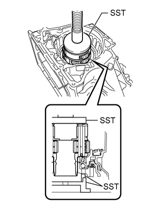 |
Using SST and a press, install a new front planetary gear assembly to the transaxle case sub-assembly.
| 19. INSTALL NO. 2 BRAKE PISTON |
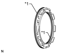 |
Coat 2 new O-rings with ATF and install them to the No. 2 brake piston.
| *1 | O-ring |
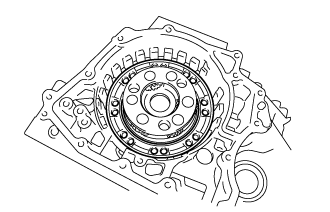 |
Install the No. 2 brake piston to the transaxle case sub-assembly.
| 20. INSTALL 1ST AND REVERSE BRAKE RETURN SPRING SUB-ASSEMBLY |
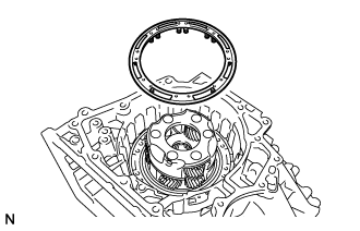 |
Install the 1st and reverse brake return spring sub-assembly to the transaxle case sub-assembly.
Place SST on the 1st and reverse brake return spring sub-assembly and compress the 1st and reverse brake return spring sub-assembly with a press.
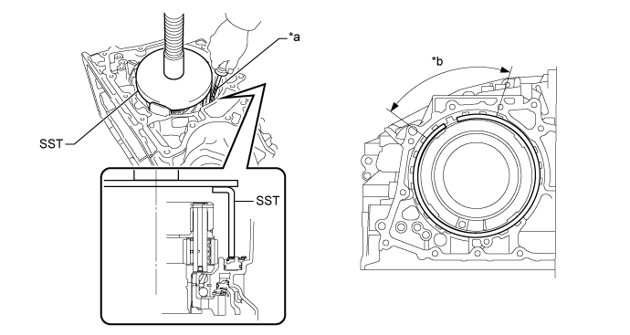
| *a | Protective Tape | *b | Snap Ring End Position |
Using a screwdriver with its tip wrapped with protective tape, install the snap ring to the transaxle case sub-assembly as shown in the illustration.
| 21. INSTALL NO. 2 BRAKE DISC |
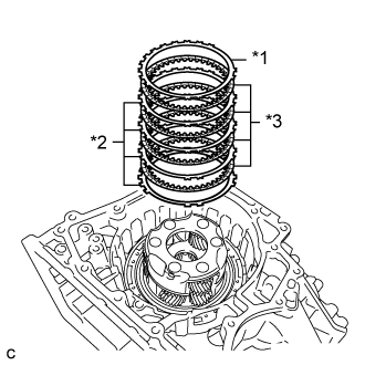 |
Install the 4 No. 2 brake discs, 4 No. 2 brake plates and No. 2 brake flange to the transaxle case sub-assembly.
| *1 | No. 2 Brake Flange |
| *2 | No. 2 Brake Plate |
| *3 | No. 2 Brake Disc |
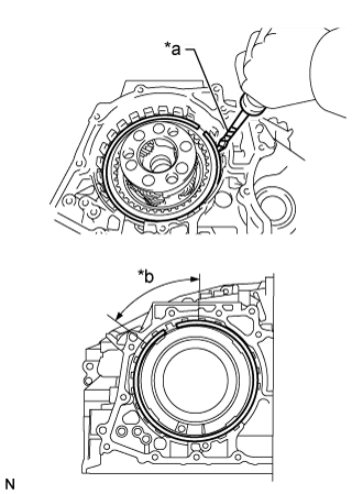 |
Using a screwdriver with its tip wrapped with protective tape, install the snap ring to the transaxle case sub-assembly.
| *a | Protective Tape |
| *b | Snap Ring End Position |
| 22. INSPECT CLEARANCE OF NO. 2 BRAKE PISTON |
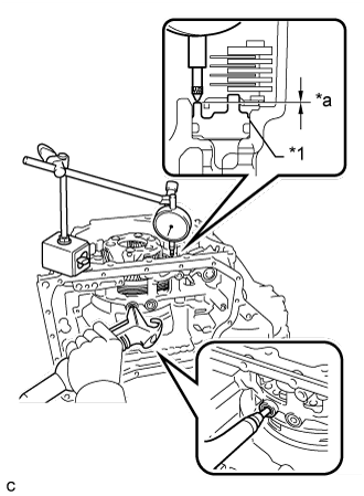 |
Apply compressed air to the oil hole shown in the illustration, and check the operation of the No. 2 brake piston.
| *1 | No. 2 Brake Piston |
| *a | Clearance |
Set a dial indicator as shown in the illustration.
Using the dial indicator, measure the clearance of the No. 2 brake piston while applying compressed air (350 kPa 3.6 kgf/cm2, 51 psi).
| Part No. | Mark | Thickness (mm (in.)) |
| 35678-33140 | 40A | 4.0 (0.157) |
| 35678-33150 | 41A | 4.1 (0.161) |
| 35678-33160 | 42A | 4.2 (0.165) |
| 35678-33170 | 43A | 4.3 (0.169) |
| 35678-33180 | 44A | 4.4 (0.173) |
| 23. INSTALL PLANETARY RING GEAR FLANGE |
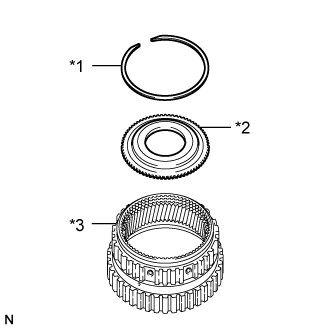 |
Install the planetary ring gear flange to the planetary ring gear.
| *1 | Snap Ring |
| *2 | Planetary Ring Gear Flange |
| *3 | Planetary Ring Gear |
Using a screwdriver with its tip wrapped with protective tape, install the snap ring to the planetary ring gear.
| 24. INSTALL ONE-WAY CLUTCH ASSEMBLY |
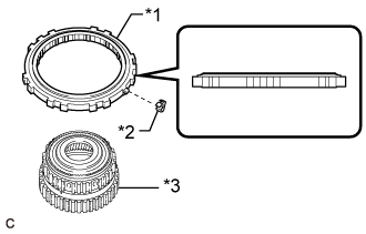 |
Install the outer race retainer to the one-way clutch assembly.
| *1 | One-way Clutch Assembly |
| *2 | Outer Race Retainer |
| *3 | Planetary Ring Gear |
Install the one-way clutch assembly to the planetary ring gear.
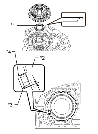 |
Coat the thrust needle roller bearing with ATF and install it to the front planetary gear assembly.
| *1 | Thrust Needle Roller Bearing |
| *2 | One-way Clutch Assembly |
| *3 | Outer Race Retainer |
| *4 | Transaxle Case Sub-assembly |
| - | Inside (mm (in.)) | Outside (mm (in.)) |
| Thrust needle roller bearing | 56.1 (2.21) | 81.1 (3.19) |
Install the one-way clutch assembly with planetary ring gear to the transaxle case sub-assembly.
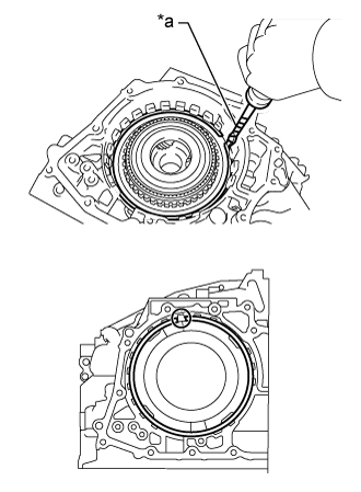 |
Using a screwdriver with its tip wrapped with protective tape, install the snap ring to the transaxle case sub-assembly.
| *a | Protective Tape |
| 25. INSTALL PARKING LOCK PAWL |
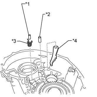 |
Install the parking lock pawl to the transaxle case sub-assembly with the parking lock pawl shaft.
| *1 | Parking Lock Pawl Pin |
| *2 | Parking Lock Pawl Shaft |
| *3 | Spring |
| *4 | Parking Lock Pawl |
Install the parking lock pawl pin to the transaxle case sub-assembly.
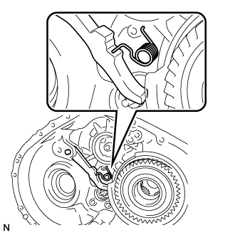 |
Install the spring to the parking lock pawl pin.
| 26. INSTALL PARKING LOCK SLEEVE |
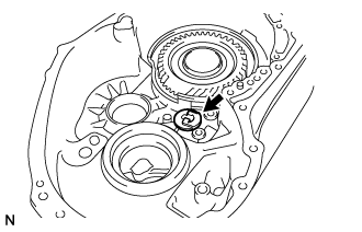 |
Install the parking lock sleeve to the transaxle case sub-assembly.
| 27. INSTALL PAWL STOPPER PLATE |
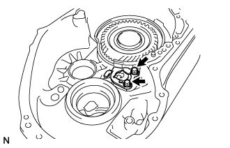 |
Install the pawl stopper plate to the transaxle case sub-assembly with the 2 bolts.
| 28. INSTALL NO. 1 TRANSMISSION CASE PLATE |
Clean and degrease the bolt and installation hole in the transaxle case sub-assembly.
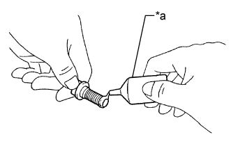 |
Apply adhesive to 2 or 3 threads on the end of the bolt.
| *a | Adhesive |
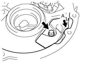 |
Install the No. 1 transmission case plate to the transaxle case sub-assembly with the bolt.
| 29. INSTALL PAWL SHAFT CLAMP |
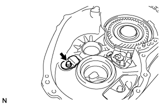 |
Install the pawl shaft clamp to the transaxle case sub-assembly with the bolt.
| 30. INSTALL COUNTER DRIVEN GEAR |
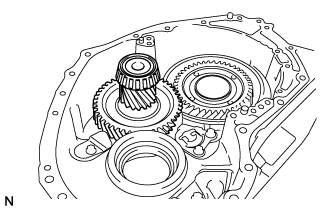 |
Install the counter driven gear to the transaxle case sub-assembly.
| 31. INSTALL COUNTER DRIVE GEAR NUT |
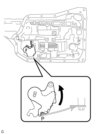 |
Turn the manual valve lever shaft sub-assembly counterclockwise to set it to the P position as shown in the illustration.
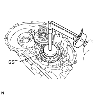 |
Using SST, install a new counter drive gear nut to the front planetary gear assembly.
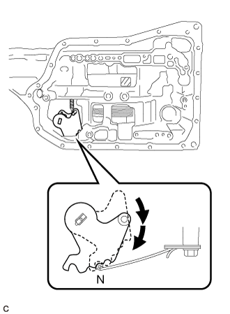 |
Turn the manual valve lever shaft sub-assembly 2 notches clockwise to set it to the N position as shown in the illustration.
Remove the counter driven gear from the transaxle case sub-assembly.
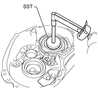 |
Using SST and a torque wrench, measure the turning torque of the bearing while rotating SST at 60 rpm.
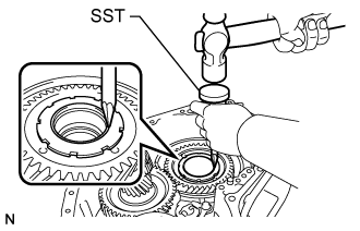 |
Using SST and a hammer, stake the front planetary gear assembly.
Install the counter driven gear to the transaxle case sub-assembly.
| 32. INSTALL FRONT DIFFERENTIAL CASE |
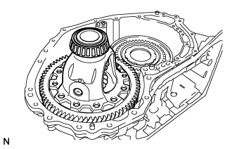 |
Install the front differential case to the transaxle case sub-assembly.
| 33. INSTALL NO. 1 BRAKE PISTON |
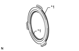 |
Coat 2 new O-rings with ATF and install them to the No. 1 brake piston.
| *1 | O-ring |
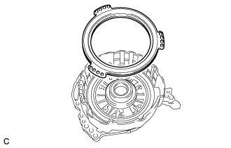 |
Install the No. 1 brake piston to the front oil pump assembly.
| 34. INSTALL 2ND BRAKE PISTON RETURN SPRING SUB-ASSEMBLY |
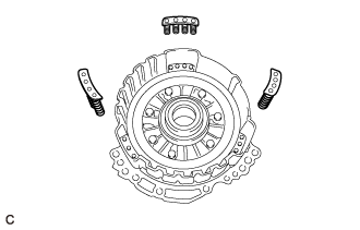 |
Install the 3 2nd brake piston return spring sub-assemblies to the front oil pump assembly.
| 35. INSTALL NO. 1 BRAKE DISC |
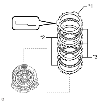 |
Install the 3 No. 1 brake discs, 3 No. 1 brake plates and No. 1 brake flange to the front oil pump assembly.
| *1 | No. 1 Brake Flange |
| *2 | No. 1 Brake Plate |
| *3 | No. 1 Brake Disc |
Place SST on the No. 1 brake flange and compress the No. 1 brake flange with a press.
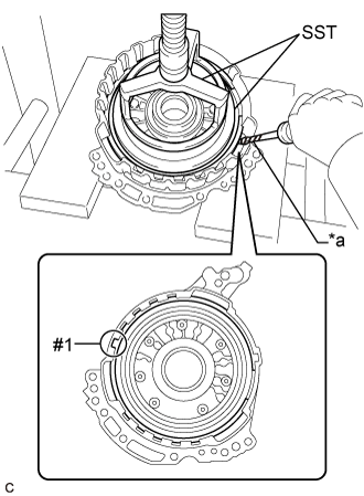 |
Using a screwdriver with its tip wrapped with protective tape, install the snap ring to the front oil pump assembly as shown in the illustration.
| *a | Protective Tape |
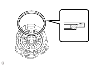 |
Install the brake snap ring stopper to the front oil pump assembly.
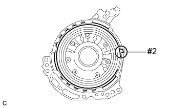 |
Using a screwdriver with its tip wrapped with protective tape, install the snap ring to the front oil pump assembly as shown in the illustration.
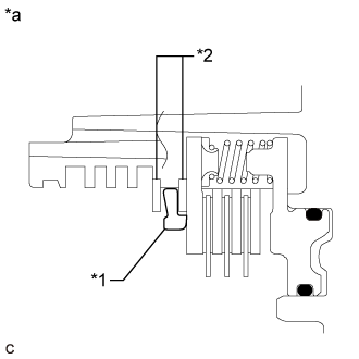 |
Check that the brake snap ring stopper can be turned by hand.
| *1 | Brake Snap Ring Stopper |
| *2 | Snap Ring |
| *a | Correctly installed |
| 36. INSPECT CLEARANCE OF NO. 1 BRAKE PISTON |
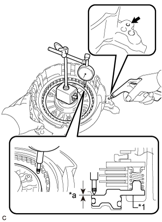 |
Apply compressed air to the oil hole shown in the illustration, and check the operation of the No. 1 brake piston.
| *1 | No. 1 Brake Piston |
| *a | Clearance |
Set a dial indicator as shown in the illustration.
Using the dial indicator, measure the clearance of the No. 1 brake piston while applying compressed air (350 kPa 3.6 kgf/cm2, 51 psi).
| Part No. | Mark | Thickness (mm (in.)) |
| 35676-73010 | 30 | 3.0 (0.118) |
| 35676-73020 | 31 | 3.1 (0.122) |
| 35676-73030 | 32 | 3.2 (0.126) |
| 35676-73040 | 33 | 3.3 (0.130) |
| 35676-73050 | 34 | 3.4 (0.134) |
| 35676-73060 | 35 | 3.5 (0.138) |
| 37. INSTALL UNDERDRIVE PLANETARY SUN GEAR |
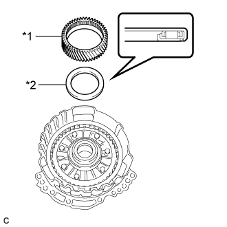 |
Coat the thrust needle roller bearing with ATF and install it to the front oil pump assembly.
| *1 | Underdrive Planetary Sun Gear |
| *2 | Thrust Needle Roller Bearing |
| - | Inside (mm (in.)) | Outside (mm (in.)) |
| Thrust needle roller bearing | 57.7 (2.27) | 75.2 (2.96) |
Install the underdrive planetary sun gear to the front oil pump assembly.
| 38. INSTALL INPUT SHAFT SUB-ASSEMBLY |
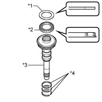 |
Coat 3 new oil seal rings with ATF and install them to the input shaft sub-assembly.
| *1 | Thrust Bearing Race |
| *2 | Thrust Needle Roller Bearing |
| *3 | Input Shaft Sub-assembly |
| *4 | Oil Seal Ring |
Coat the thrust needle roller bearing and thrust bearing race with ATF and install them to the input shaft sub-assembly.
| - | Inside (mm (in.)) | Outside (mm (in.)) |
| Thrust needle roller bearing | 29.1 (1.15) | 48.6 (1.91) |
| Thrust bearing race | 30.7 (1.21) | 48.3 (1.90) |
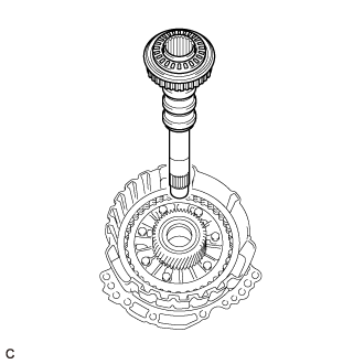 |
Install the input shaft sub-assembly to the front oil pump assembly.
| 39. INSTALL PLANETARY SUN GEAR SUB-ASSEMBLY |
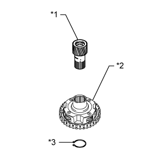 |
Using a snap ring expander, install the snap ring to the underdrive planetary gear assembly.
| *1 | Planetary Sun Gear Sub-assembly |
| *2 | Underdrive Planetary Gear Assembly |
| *3 | Snap Ring |
Using a snap ring expander, install the planetary sun gear sub-assembly to the underdrive planetary gear assembly with the snap ring expanded.
| 40. INSTALL UNDERDRIVE PLANETARY RING GEAR |
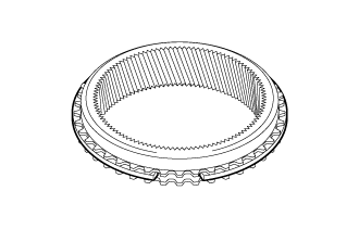 |
Install the snap ring to the underdrive planetary ring gear.
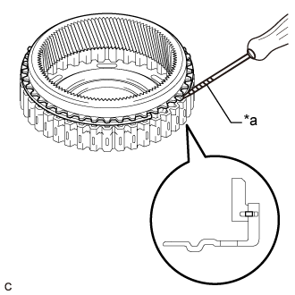 |
While compressing the snap ring with a screwdriver with its tip wrapped with protective tape, install the underdrive planetary ring gear to the No. 3 brake hub.
| *a | Protective Tape |
| 41. INSTALL NO. 3 BRAKE HUB |
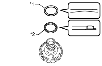 |
Coat the thrust needle roller bearing and thrust bearing race with ATF and install them to the underdrive planetary gear assembly.
| *1 | Thrust Bearing Race |
| *2 | Thrust Needle Roller Bearing |
| - | Inside (mm (in.)) | Outside (mm (in.)) |
| Thrust needle roller bearing | 62.6 (2.46) | 82.4 (3.24) |
| Thrust bearing race | 65.9 (2.59) | 82.3 (3.24) |
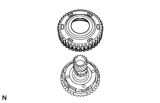 |
Install the No. 3 brake hub to the underdrive planetary gear assembly.
| 42. INSTALL UNDERDRIVE PLANETARY GEAR ASSEMBLY |
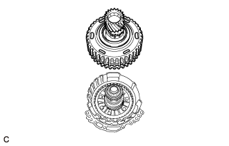 |
Install the underdrive planetary gear assembly to the front oil pump assembly.
| 43. INSTALL NO. 3 BRAKE DISC |
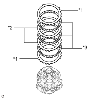 |
Install the 2 No. 3 brake flanges, 3 No. 3 brake discs and 2 No. 3 brake plates to the front oil pump assembly.
| *1 | No. 3 Brake Flange |
| *2 | No. 3 Brake Plate |
| *3 | No. 3 Brake Disc |
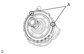 |
Using a screwdriver with its tip wrapped with protective tape, install the snap ring to the front oil pump assembly.
| 44. INSPECT CLEARANCE OF NO. 3 BRAKE PISTON |
Using a vernier caliper and a straightedge, measure the distance shown in the illustration (Dimension (A)) while a load of 500 N (51 kgf, 112.4 lbf) is being applied to the No. 3 brake flange.
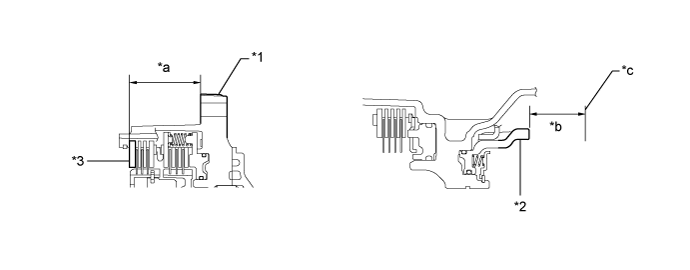
| *1 | Front Oil Pump Assembly | *2 | No. 3 Brake Piston |
| *3 | No. 3 Brake Flange | - | - |
| *a | Dimension (A) | *b | Dimension (B) |
| *c | Contact Surface of Front Oil Pump Assembly | - | - |
Using a vernier caliper and a straightedge, measure the distance shown in the illustration (Dimension (B)).
Calculate the clearance using the following formula:
Clearance = Dimension (B) - Dimension (A)
Adjust clearance of No. 3 brake piston:
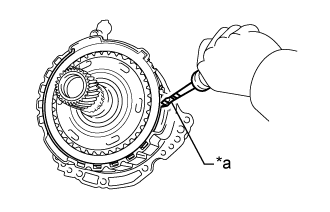 |
Using a screwdriver with its tip wrapped with protective tape, remove the snap ring from the front oil pump assembly.
| *a | Protective Tape |
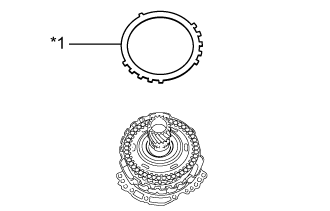 |
Remove the No. 3 brake flange from the front oil pump assembly.
| *1 | No. 3 Brake Flange |
Using a vernier caliper and a straightedge, measure the distance shown in the illustration (Dimension (A)) while a load of 500 N (51 kgf, 112.4 lbf) is being applied to the No. 3 brake disc.
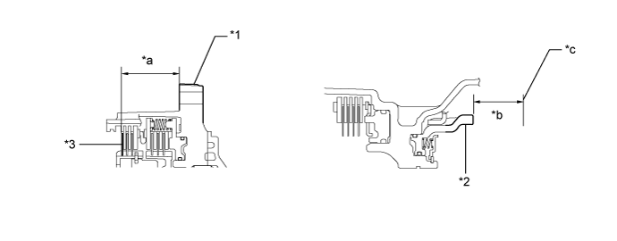
| *1 | Front Oil Pump Assembly | *2 | No. 3 Brake Piston |
| *3 | No. 3 Brake Disc | - | - |
| *a | Dimension (A) | *b | Dimension (B) |
| *c | Contact Surface of Front Oil Pump Assembly | - | - |
Using a vernier caliper and a straightedge, measure the distance shown in the illustration (Dimension (B)).
Calculate the thickness of the replacement No. 3 brake flange using the following formula:
| Part No. | Mark | Thickness (mm (in.)) |
| 35679-73020 | 38 | 3.8 (0.150) |
| 35679-73030 | 39 | 3.9 (0.154) |
| 35679-73040 | 40 | 4.0 (0.157) |
| 35679-73050 | 41 | 4.1 (0.161) |
| 35679-73060 | 42 | 4.2 (0.165) |
| 35679-73070 | 43 | 4.3 (0.169) |
| 35679-73080 | 44 | 4.4 (0.173) |
|
Install the No. 3 brake flange to the front oil pump assembly.
| *1 | No. 3 Brake Flange |
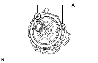 |
Using a screwdriver with its tip wrapped with protective tape, install the snap ring to the front oil pump assembly.
| 45. INSTALL FRONT OIL PUMP ASSEMBLY |
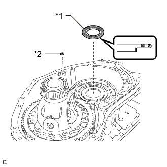 |
Coat a new O-ring with ATF and install it to the transaxle case sub-assembly.
| *1 | Thrust Needle Roller Bearing |
| *2 | O-ring |
Coat the thrust needle roller bearing with ATF.
Install the thrust needle roller bearing to the counter drive gear nut.
| - | Inside (mm (in.)) | Outside (mm (in.)) |
| Thrust needle roller bearing | 53.46 (2.10) | 79 (3.11) |
Coat the thrust bearing race with MP grease.
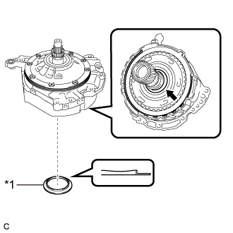 |
Install the thrust bearing race to the underdrive planetary gear assembly.
| *1 | Thrust Bearing Race |
| - | Inside (mm (in.)) | Outside (mm (in.)) |
| Thrust bearing race | 59.4 (2.34) | 76 (2.99) |
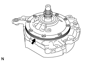 |
Coat a new front oil pump body O-ring with ATF and install it to the front oil pump body sub-assembly.
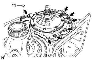 |
Install the front oil pump assembly to the transaxle case sub-assembly with the 7 bolts.
| *1 | Gasket |
Coat a new gasket with ATF and install it to the front oil pump assembly.
| 46. INSTALL TRANSAXLE HOUSING OIL SEPARATOR |
Clean and degrease the 3 bolts and installation holes in the transaxle housing.
|
Apply adhesive to 2 or 3 threads on the ends of the 3 bolts.
| *a | Adhesive |
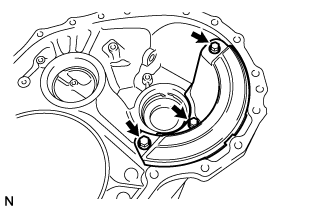 |
Install the transaxle housing oil separator to the transaxle housing with the 3 bolts.
| 47. INSTALL DIFFERENTIAL GEAR LUBE APPLY TUBE |
Clean and degrease the bolt and installation hole in the transaxle housing.
|
Apply adhesive to 2 or 3 threads on the end of the bolt.
| *a | Adhesive |
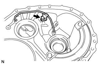 |
Install the differential gear lube apply tube to the transaxle housing.
Install the clamp to the transaxle housing with the bolt.
| 48. INSTALL TRANSAXLE HOUSING |
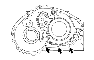 |
Clean and degrease the 3 bolts and installation holes in the transaxle case sub-assembly.
Remove any remaining seal packing from the contact surfaces of the transaxle housing and transaxle case sub-assembly.
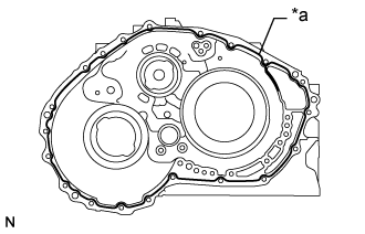 |
Apply FIPG to the transaxle case sub-assembly.
| *a | FIPG |
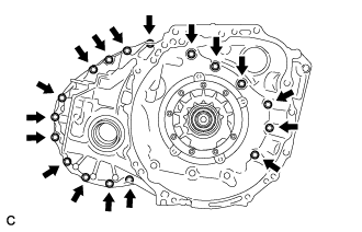 |
Install the transaxle housing to the transaxle case sub-assembly with the 17 bolts.
|
Apply adhesive to 2 or 3 threads on the ends of the 3 bolts.
| *a | Adhesive |
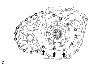 |
Install the 3 bolts.
| 49. INSPECT CLEARANCE OF NO. 1 CLUTCH |
Install the rear multiple disc clutch assembly to the rear transaxle cover sub-assembly.
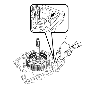 |
Check that the piston moves when compressed air (200 kPa, 2.0 kgf/cm2, 29 psi) is applied to the oil hole.
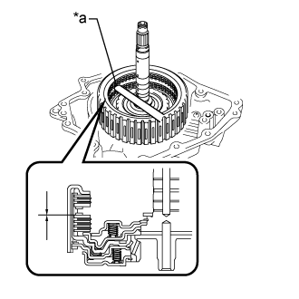 |
Using a feeler gauge, measure the No. 1 clutch pack clearance.
| *a | Feeler Gauge |
| 50. INSTALL REAR PLANETARY SUN GEAR ASSEMBLY |
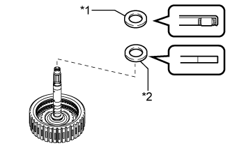 |
Coat the thrust needle roller bearing and thrust bearing race with ATF and install them to the rear multiple disc clutch assembly.
| *1 | Thrust Needle Roller Bearing |
| *2 | Thrust Bearing Race |
| - | Inside (mm (in.)) | Outside (mm (in.)) |
| Thrust needle roller bearing | 28 (1.10) | 47.1 (1.85) |
| Thrust bearing race | 26.1 (1.03) | 44 (1.73) |
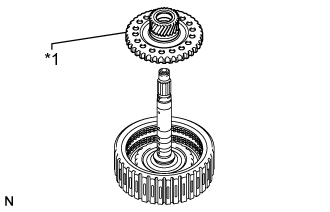 |
Install the rear planetary sun gear assembly to the rear multiple disc clutch assembly.
| *1 | Rear Planetary Sun Gear Assembly |
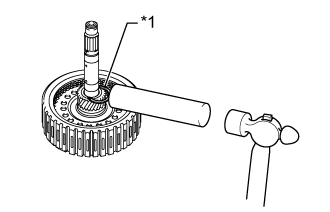 |
Using a brass bar and a hammer, install the snap ring to the rear multiple disc clutch assembly.
| *1 | Snap Ring |
| 51. INSPECT CLEARANCE OF NO. 2 CLUTCH |
Install the rear multiple disc clutch assembly to the rear transaxle cover sub-assembly.
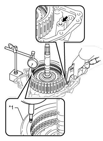 |
Using a dial indicator, measure the No. 2 clutch pack clearance while applying compressed air (200 kPa, 2.0 kgf/cm2, 29 psi).
| *1 | No. 2 Direct Clutch Piston |
| 52. INSTALL REAR MULTIPLE DISC CLUTCH ASSEMBLY |
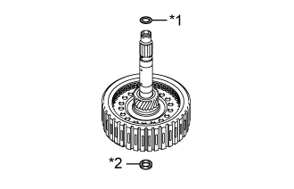 |
Coat a new O-ring with ATF and install it to the rear multiple disc clutch assembly.
| *1 | O-ring |
| *2 | Oil Seal Ring |
Coat a new oil seal ring with ATF and install it to the rear multiple disc clutch assembly.
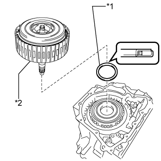 |
Coat the thrust needle roller bearing with ATF and install it to the transaxle case sub-assembly.
| *1 | Thrust Needle Roller Bearing |
| *2 | Rear Multiple Disc Clutch Assembly |
| - | Inside (mm (in.)) | Outside (mm (in.)) |
| Thrust needle roller bearing | 61.2 (2.41) | 79 (3.11) |
Install the rear multiple disc clutch assembly to the transaxle case sub-assembly.
| 53. INSPECT INTERMEDIATE SHAFT END PLAY |
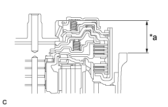 |
Clean the contact surfaces of the transaxle case sub-assembly and rear transaxle cover sub-assembly.
Place a straightedge on the multiple direct clutch drum and measure the distance between the transaxle case sub-assembly and the straightedge (Dimension (A)) using a vernier caliper.
| *a | Dimension (A) |
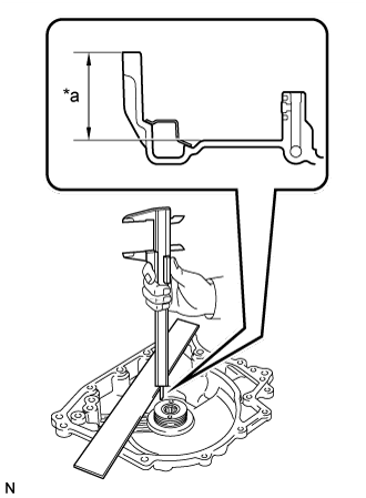 |
Using a vernier caliper and a straightedge, measure the distance shown in the illustration (Dimension (B)).
| *a | Dimension (B) |
Calculate the end play using the following formula:
End play = Dimension (B) - Dimension (A) - Thrust needle roller bearing thickness
| 54. INSTALL REAR TRANSAXLE COVER SUB-ASSEMBLY |
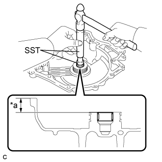 |
Using SST and a hammer, install a new needle roller bearing to the rear transaxle cover sub-assembly.
| *a | Depth |
Clean and degrease the 2 "TORX" screws and installation holes in the rear transaxle cover sub-assembly.
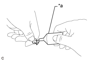 |
Apply adhesive to 2 or 3 threads on the ends of the 2 "TORX" screws.
| *a | Adhesive |
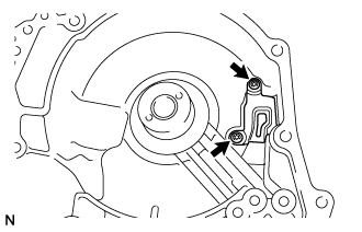 |
Using a T30 "TORX" socket wrench, install the rear transaxle cover plate to the rear transaxle cover sub-assembly with the 2 "TORX" screws.
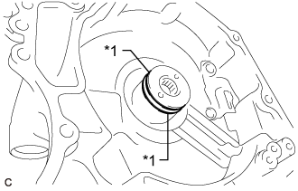 |
Coat 2 new oil seal rings with ATF and install them to the rear transaxle cover sub-assembly.
| *1 | Oil Seal Ring |
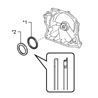 |
Coat the thrust needle roller bearing and thrust bearing race with MP grease and install them to the rear transaxle cover sub-assembly.
| *1 | Thrust Needle Roller Bearing |
| *2 | Thrust Bearing Race |
| - | Inside (mm (in.)) | Outside (mm (in.)) |
| Thrust needle roller bearing | 48.9 (1.93) | 72.0 (2.83) |
| Thrust bearing race | 52.2 (2.06) | 70.4 (2.77) |
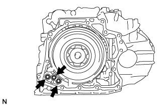 |
Coat 3 new O-rings with ATF and install them to the transaxle case sub-assembly.
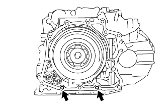 |
Clean and degrease the 2 bolts and installation holes in the transaxle case sub-assembly.
Remove any remaining seal packing from the contact surfaces of the rear transaxle cover sub-assembly and transaxle case sub-assembly.
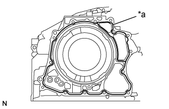 |
Apply FIPG to the transaxle case sub-assembly.
| *a | FIPG |
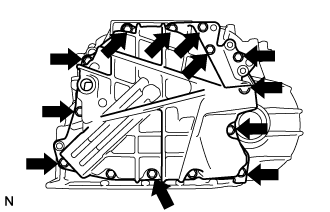 |
Install the rear transaxle cover sub-assembly to the transaxle case sub-assembly with the 12 bolts.
|
Apply adhesive to 2 or 3 threads on the ends of the 2 bolts.
| *a | Adhesive |
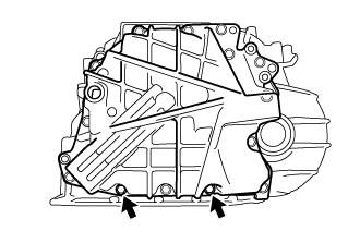 |
Install the 2 bolts.
| 55. INSTALL REAR TRANSAXLE COVER PLUG |
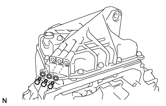 |
Coat 3 new O-rings with ATF and install them to the 3 rear transaxle cover plugs.
Install the 3 rear transaxle cover plugs to the rear transaxle cover sub-assembly.
| 56. INSTALL REFILL PLUG |
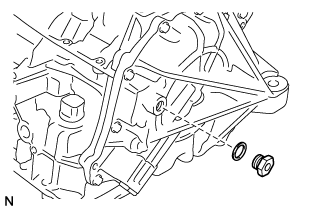 |
Install a new gasket to the refill plug.
Install the refill plug to the rear transaxle cover sub-assembly.
| 57. INSPECT INPUT SHAFT SUB-ASSEMBLY END PLAY |
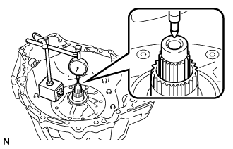 |
Using a dial indicator, measure the input shaft sub-assembly end play.
| 58. INSTALL TRANSAXLE CASE GASKET |
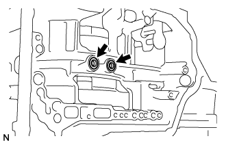 |
Coat 2 new transaxle case gaskets with ATF.
Install the 2 transaxle case gaskets to the transaxle case sub-assembly.
| 59. INSTALL TRANSMISSION VALVE BODY ASSEMBLY |
Coat the O-ring of the transmission wire with ATF.
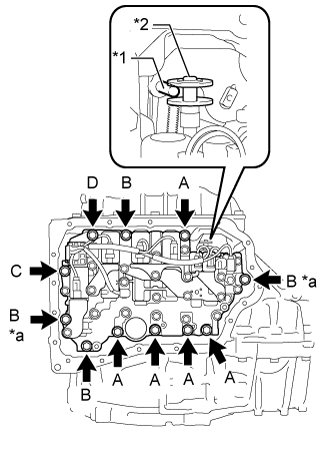 |
Insert the manual valve lever shaft sub-assembly pin into the groove on the end of the manual valve as shown in the illustration and temporarily install the transmission valve body assembly to the transaxle case sub-assembly with the 11 bolts.
| *1 | Manual Valve Lever Shaft Sub-assembly Pin |
| *2 | Manual Valve |
| *a | Positioning Bolt |
| Bolt | Bolt Length (mm (in.)) |
| (A) | 25 (0.984) |
| (B) | 30 (1.18) |
| (C) and (D) | 35 (1.38) |
Fully tighten the 2 positioning bolts shown in the illustration.
Fully tighten the 9 bolts to install the transmission valve body assembly.
| 60. INSTALL VALVE BODY OIL STRAINER ASSEMBLY |
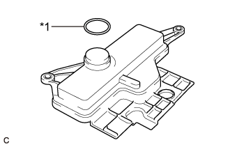 |
Coat a new O-ring with ATF.
| *1 | O-ring |
Install the O-ring to the valve body oil strainer assembly.
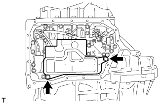 |
Install the valve body oil strainer assembly to the transmission valve body assembly with the 2 bolts.
| 61. INSTALL TRANSMISSION OIL CLEANER MAGNET |
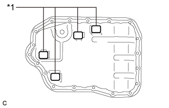 |
Install the 4 transmission oil cleaner magnets to the automatic transaxle oil pan sub-assembly as shown in the illustration.
| *1 | Transmission Oil Cleaner Magnet |
| 62. INSTALL AUTOMATIC TRANSAXLE OIL PAN GASKET |
Install a new automatic transaxle oil pan gasket to the automatic transaxle oil pan sub-assembly.
| 63. INSTALL AUTOMATIC TRANSAXLE OIL PAN SUB-ASSEMBLY |
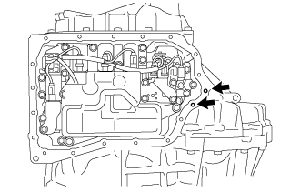 |
Clean and degrease the 2 bolts and installation holes in the transaxle case sub-assembly.
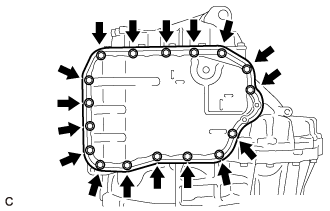 |
Install the automatic transaxle oil pan sub-assembly with automatic transaxle oil pan gasket to the transaxle case sub-assembly with the 17 bolts.
|
Apply adhesive to 2 or 3 threads on the ends of the 2 bolts.
| *a | Adhesive |
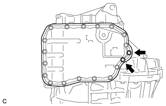 |
Install the 2 bolts.
| 64. INSTALL NO. 1 TRANSMISSION OIL FILLER TUBE |
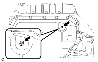 |
Using a 6 mm hexagon socket wrench, install the No. 1 transmission oil filler tube to the automatic transaxle oil pan sub-assembly.
| 65. INSTALL OVERFLOW PLUG |
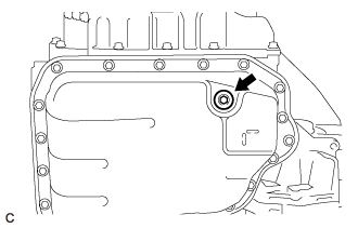 |
Using a 6 mm hexagon socket wrench, install the overflow plug and a new gasket to the automatic transaxle oil pan sub-assembly.
| 66. INSTALL FRONT DRIVE SHAFT OIL SEAL LH |
Coat the lip of a new front drive shaft oil seal LH with MP grease.
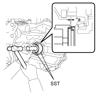 |
Using SST and a hammer, install the front drive shaft oil seal LH to the transaxle case sub-assembly.
| *a | Depth |
| 67. INSTALL FRONT DRIVE SHAFT OIL SEAL RH |
Coat the lip of a new front drive shaft oil seal RH with MP grease.
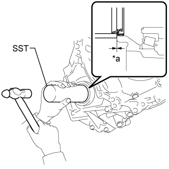 |
Using SST and a hammer, install the front drive shaft oil seal RH to the transaxle housing.
| *a | Depth |
| 68. INSTALL NO. 2 TRANSAXLE CASE PLUG |
Clean and degrease the 3 No. 2 transaxle case plugs and installation holes in the transaxle housing.
Install 3 new gaskets to the 3 No. 2 transaxle case plugs.
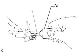 |
Apply adhesive to 2 or 3 threads on the ends of the 3 No. 2 transaxle case plugs.
| *a | Adhesive |
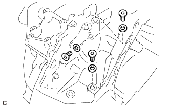 |
Using a 6 mm hexagon socket wrench, install the 3 No. 2 transaxle case plugs to the transaxle housing.
| 69. INSTALL NO. 1 TRANSAXLE CASE PLUG |
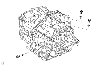 |
Coat 3 new O-rings with ATF and install them to the 3 No. 1 transaxle case plugs.
Install the 3 No. 1 transaxle case plugs to the transaxle case sub-assembly.
| 70. INSTALL OIL COOLER INLET ELBOW |
Coat a new O-ring with ATF and install it to the oil cooler inlet elbow.
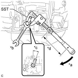 |
Using SST, install the oil cooler inlet elbow to the transaxle case sub-assembly so that it is positioned as shown in the illustration.
| *a | Turn |
| *b | Hold |
| *c | 20 to 24° |
| *d | Torque Wrench Fulcrum Length |
| 71. INSTALL OIL COOLER UNION SUB-ASSEMBLY |
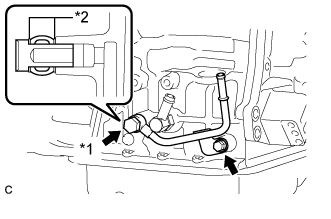 |
Temporarily install the oil cooler union sub-assembly to the transaxle case sub-assembly with the bolt.
| *1 | Union Bolt |
| *2 | Gasket |
Install the union bolt and 2 new gaskets to the transaxle case sub-assembly as shown in the illustration.
Tighten the bolt.
| 72. INSTALL PARK/NEUTRAL POSITION SWITCH ASSEMBLY |
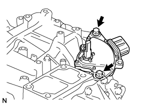 |
Temporarily install the park/neutral position switch assembly to the transaxle case sub-assembly with the 2 bolts.
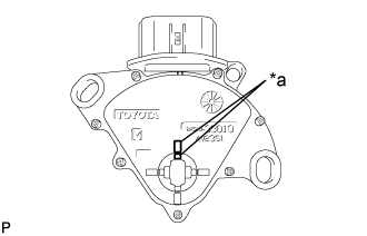 |
Align the protrusions of the park/neutral position switch assembly as shown in the illustration.
| *a | Protrusion |
Tighten the 2 bolts.
| 73. INSTALL TRANSMISSION CONTROL SHAFT LEVER |
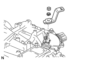 |
Install the transmission control shaft lever to the manual valve lever shaft sub-assembly with the washer and nut.
| 74. INSTALL TRANSMISSION BREATHER HOSE SUB-ASSEMBLY |
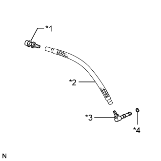 |
Coat a new O-ring with ATF and install it to the No. 2 breather plug.
| *1 | No. 1 Breather Plug |
| *2 | Breather Plug Hose |
| *3 | No. 2 Breather Plug |
| *4 | O-ring |
Install the No. 2 breather plug to the breather plug hose.
Install the No. 1 breather plug to the breather plug hose.
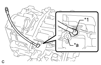 |
Install the transmission breather hose sub-assembly to the transaxle case sub-assembly.
| *1 | No. 2 Breather Plug |
| *a | Boss |