 |
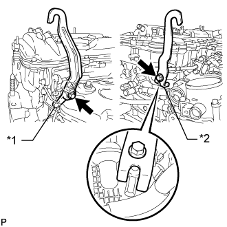
Remove the 2 bolts, No. 1 engine hanger and No. 2 engine hanger.
| *1 | No. 1 Engine Hanger |
| *2 | No .2 Engine Hanger |
ENGINE UNIT > REMOVAL |
| 1. REMOVE ENGINE HANGERS |
|
Remove the 2 bolts, No. 1 engine hanger and No. 2 engine hanger.
| *1 | No. 1 Engine Hanger |
| *2 | No .2 Engine Hanger |
| 2. REMOVE ENGINE OIL LEVEL DIPSTICK GUIDE |
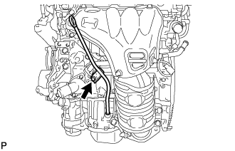 |
Remove the engine oil level dipstick.
Remove the bolt and engine oil level dipstick guide.
Remove the O-ring from the engine oil level dipstick guide.
| 3. REMOVE MANIFOLD STAY |
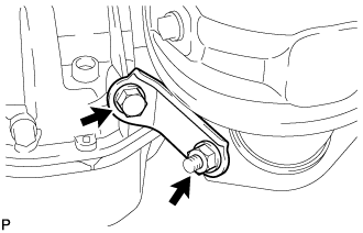 |
Remove the bolt, nut and manifold stay.
| 4. REMOVE NO. 2 MANIFOLD STAY |
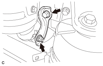 |
Remove the bolt, nut and No. 2 manifold stay.
| 5. REMOVE NO. 1 EXHAUST MANIFOLD HEAT INSULATOR |
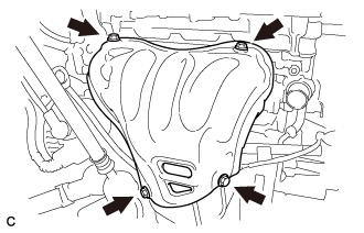 |
Remove the 4 bolts and No. 1 exhaust manifold heat insulator.
| 6. REMOVE EXHAUST MANIFOLD CONVERTER SUB-ASSEMBLY |
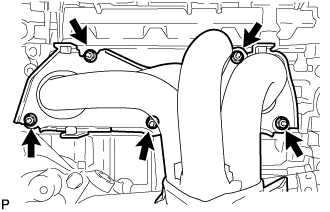 |
Remove the 5 nuts and exhaust manifold converter sub-assembly.
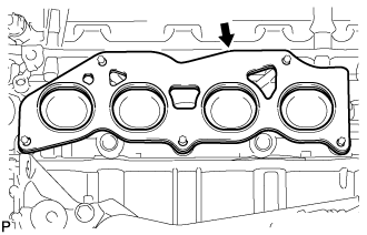 |
Remove the exhaust manifold to head gasket.
| 7. REMOVE NO. 1 COMPRESSOR MOUNTING BRACKET |
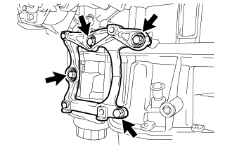 |
Remove the 4 bolts and bracket.
| 8. REMOVE THROTTLE WITH MOTOR BODY ASSEMBLY |
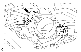 |
Disconnect the fuel tube from the clamp.
Disconnect the throttle body connector.
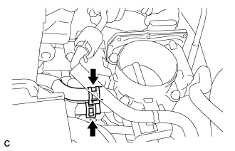 |
Disconnect the water by-pass hose from the throttle with motor body assembly.
Disconnect the No. 2 water by-pass hose from the throttle with motor body assembly.
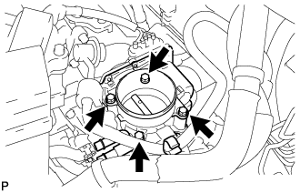 |
Remove the 4 bolts and the throttle body with fuel tube bracket.
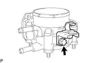 |
Remove the bolt and fuel tube bracket.
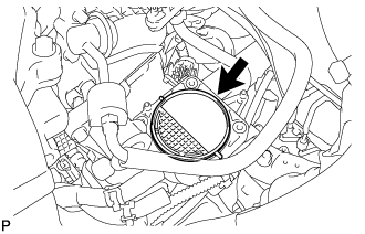 |
Remove the gasket from the intake manifold.
| 9. REMOVE WATER BY-PASS HOSE |
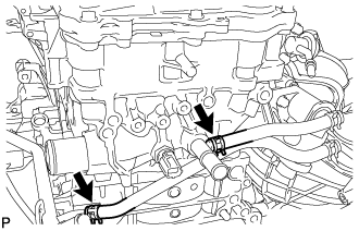 |
Remove the No. 1 and No. 2 water by-pass hoses.
| 10. REMOVE VACUUM SWITCHING VALVE ASSEMBLY (for ACIS) |
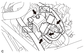 |
Disconnect the union to connector tube hose and wire harness clamp.
Disconnect the 2 vacuum hoses and connector.
Remove the bolt and vacuum switching valve assembly.
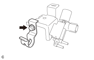 |
Remove the bolt and vacuum hose clamp.
| 11. DISCONNECT NO. 2 VENTILATION HOSE |
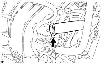 |
Disconnect the No. 2 ventilation hose from the intake manifold.
| 12. DISCONNECT UNION TO CONNECTOR TUBE HOSE |
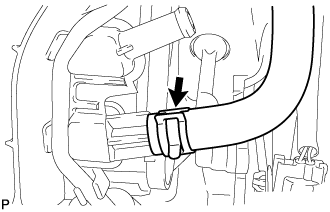 |
Disconnect the union to connector tube hose from the intake manifold.
| 13. REMOVE FUEL DELIVERY PIPE SUB-ASSEMBLY |
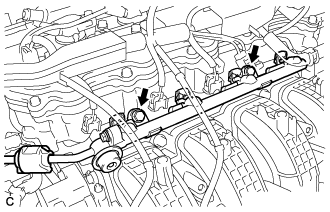 |
Remove the 2 bolts and fuel delivery pipe sub-assembly with the 4 fuel injector assemblies.
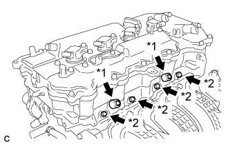 |
Remove the 2 fuel delivery spacers from the cylinder head.
| *1 | Fuel Delivery Spacer |
| *2 | Injector Vibration Insulator |
Remove the 4 injector vibration insulators from the cylinder head.
| 14. REMOVE INTAKE MANIFOLD |
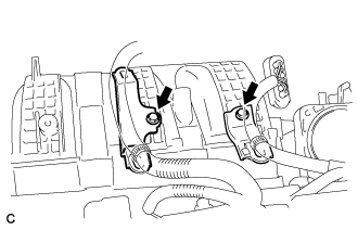 |
Remove the 2 bolts and 2 wire harness clamp brackets.
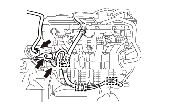 |
Disconnect the fuel vapor feed hose.
Disconnect the 3 wire harness clamps and connector.
Remove the bolt and wire harness clamp bracket.
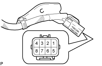 |
Apply battery voltage to the terminals of the connector to close the tumble control valves (w/ TCV).
| Tester Connection | Specified Condition |
| Positive (+) battery voltage applied to terminal 8 (M-), and negative (-) battery voltage applied to terminal 4 (M+) | Open → Closed |
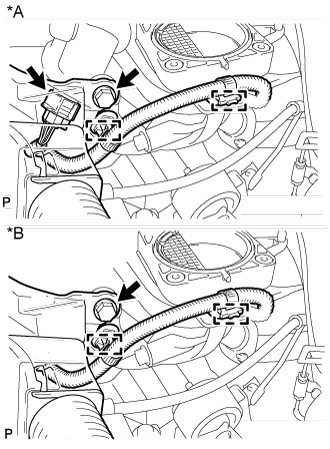 |
Remove the bolt and separate the wire harness.
Disconnect the 2 wire harness clamps and intake air control valve actuator connector (w/ TCV).
Disconnect the 2 wire harness clamps (w/o TCV).
| *A | w/ TCV |
| *B | w/o TCV |
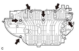 |
Remove the 6 bolts and intake manifold (w/ TCV).
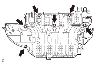 |
Remove the 6 bolts and intake manifold (w/o TCV).
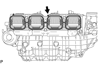 |
Remove the intake manifold gasket from the intake manifold (w/ TCV).
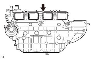 |
Remove the intake manifold gasket from the intake manifold (w/o TCV).
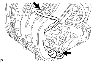 |
Disconnect the 2 vacuum hoses from the intake manifold and remove the No. 1 check valve.
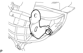 |
Remove the bolt and wire harness clamp bracket.
| 15. REMOVE SENSOR WIRE |
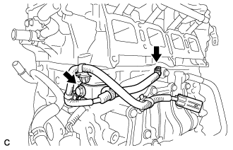 |
Disconnect the knock control sensor connector.
Remove the bolt and knock control sensor wire.
| 16. REMOVE KNOCK CONTROL SENSOR |
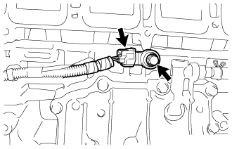 |
Disconnect the sensor connector.
Remove the bolt and knock control sensor.
| 17. REMOVE ENGINE OIL PRESSURE SWITCH ASSEMBLY |
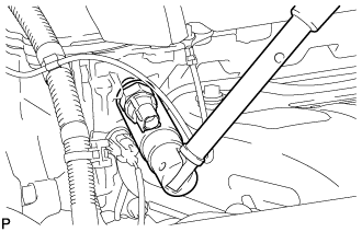 |
Disconnect the connector.
Using a 24 mm deep socket wrench, remove the oil pressure switch.
| 18. REMOVE ENGINE COOLANT TEMPERATURE SENSOR |
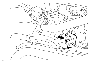 |
Disconnect the engine coolant temperature sensor connector.
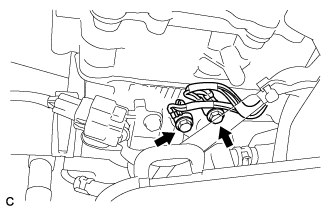 |
Remove the 2 bolts and disconnect the wire harness.
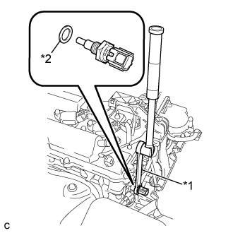 |
Using a 19 mm ball joint lock nut wrench, remove the engine coolant temperature sensor.
| *1 | Ball Joint Lock Nut Wrench |
| *2 | Gasket |
Remove the gasket from the engine coolant temperature sensor.
| 19. REMOVE IGNITION COIL ASSEMBLY |
Disconnect the 4 ignition coil assembly connectors.
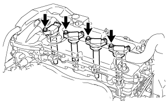 |
Remove the 4 bolts and 4 ignition coil assemblies.