 |
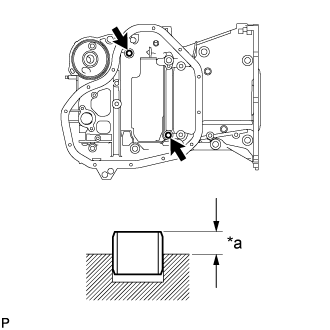
Using a plastic-faced hammer, tap in 2 new ring pins until they stop.
- Standard protrusion height:
- 4.3 to 5.3 mm (0.169 to 0.209 in.)
| *a | Protrusion Height |
ENGINE UNIT > REASSEMBLY |
| 1. INSTALL STIFFENING CRANKCASE RING PIN |
|
Using a plastic-faced hammer, tap in 2 new ring pins until they stop.
| *a | Protrusion Height |
| 2. INSTALL ENGINE BALANCER ASSEMBLY |
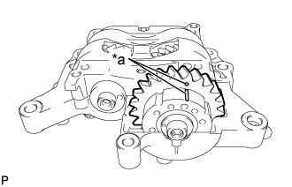 |
Check that the alignment marks of the balance shaft damper cover and balance shaft driven gear are aligned.
| *a | Alignment Mark |
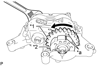 |
Place a wrench on the rear cutout part of the No. 2 balance shaft and secure the shaft in place.
| *1 | Driven Gear |
| *2 | Damper Cover |
| *a | Alignment Mark |
Rotate the balance shaft driven gear of the No. 1 balance shaft counterclockwise to align the alignment mark of the balance shaft driven gear with the alignment mark of the balance shaft damper cover.
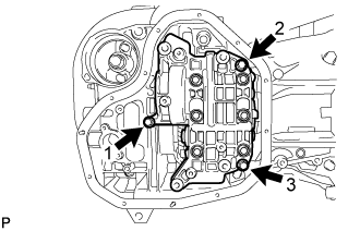 |
Install the engine balancer to the stiffening crankcase with the 3 bolts, and tighten the bolts in the sequence shown in the illustration.
| 3. INSTALL STIFFENING CRANKCASE STUD BOLT |
Using an E5 and E8 "TORX" socket wrench, install the stud bolts.
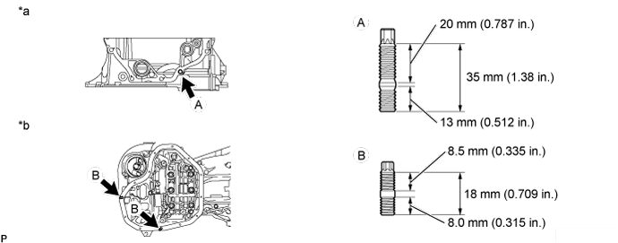
| *a | Front Side | *b | Lower Side |
| 4. INSTALL STIFFENING CRANKCASE ASSEMBLY |
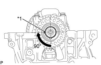 |
Rotate the crankshaft clockwise so that the crankshaft key is at the position 90° from the bottom as shown in the illustration.
| *1 | Key |
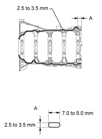 |
Apply seal packing in a continuous line as shown in the illustration.
| Area | Specified Condition |
| Continuous Line | 2.5 to 3.5 mm (0.0984 to 0.138 in.) |
| Dashed Line | 7.0 to 9.0 mm (0.276 to 0.354 in.) wide and 2.5 to 3.5 mm (0.0984 to 0.138 in.) thick |
 | Stiffening Crankcase |
 | Cylinder Block |
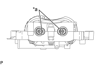 |
Check that the rear cutout parts are as shown in the illustration.
| *a | Cutout |
Clean the bolts and their installation holes.
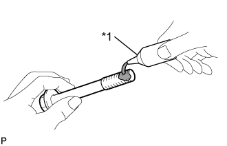 |
Apply adhesive to 3 or more threads of the ends of bolts A.
| *1 | Adhesive |
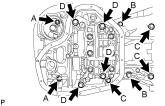 |
Temporarily install the stiffening crankcase with the 11 bolts.
| Item | Length |
| Bolt A | 65 mm (2.56 in.) |
| Bolt B | 35 mm (1.38 in.) |
| Bolt C | 125 mm (4.92 in.) |
| Bolt D | 165 mm (6.50 in.) |
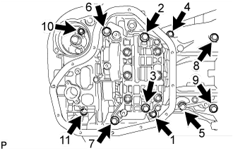 |
Tighten the 11 bolts in the sequence shown in the illustration to install the stiffening crankcase
| 5. INSTALL NO. 1 OIL PAN BAFFLE PLATE |
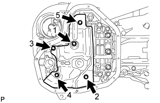 |
Install the oil pan baffle plate and uniformly tighten the 5 bolts in several steps, in the sequence shown in the illustration.
| 6. INSTALL OIL STRAINER SUB-ASSEMBLY |
Apply a light coat of engine oil to a new gasket.
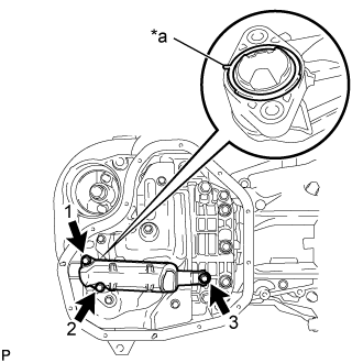 |
Align the protrusion of the gasket with the cutout of the oil strainer, and install the gasket to the oil strainer.
| *a | Protrusion |
Install the oil strainer with the 3 bolts in several steps, in the sequence shown in the illustration.
| 7. INSTALL OIL PAN SUB-ASSEMBLY |
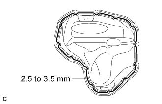 |
Apply seal packing in a continuous line as shown in the illustration.
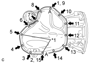 |
Install the oil pan with the 11 bolts and 2 nuts in several steps, in the sequence shown in the illustration.
| *1 | Nut |
| 8. INSTALL OIL FILTER CAP ASSEMBLY |
Clean the inside of the oil filter cap, threads and O-ring groove.
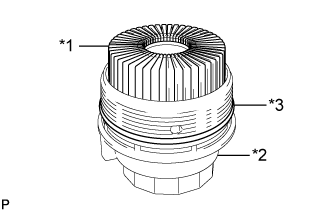 |
Apply a small amount of engine oil to a new O-ring and install it to the oil filter cap.
| *1 | Oil Filter Element |
| *2 | Oil Filter Cap |
| *3 | O-ring |
Set a new oil filter element into the oil filter cap.
Remove any dirt or foreign matter from the installation surface of the engine.
Apply a small amount of engine oil to the O-ring again and temporarily install the oil filter cap.
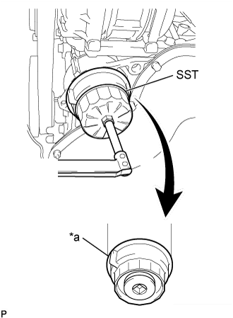 |
Using SST, tighten the oil filter cap.
| *a | No Clearance |
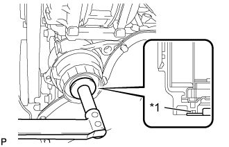 |
Apply a small amount of engine oil to a new O-ring, and install it to the oil filter cap.
| *1 | O-ring |
Install the oil filter drain plug.
| 9. INSTALL REAR ENGINE OIL SEAL |
Apply MP grease to the lip of a new oil seal.
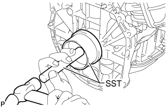 |
Using SST and a hammer, tap in the oil seal until its surface is flush with the edges of the cylinder block and crankcase.
| 10. INSTALL CYLINDER BLOCK WATER JACKET SPACER |
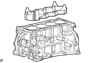 |
Install the water jacket spacer to the cylinder block.
| 11. INSTALL CYLINDER HEAD GASKET |
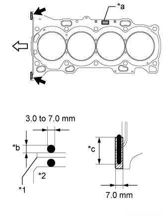 |
Clean the cylinder block sub-assembly and cylinder head sub-assembly with solvent.
| *1 | Cylinder Head Gasket |
| *2 | Cylinder Block Sub-assembly |
| *a | Lot No. |
| *b | 3.0 mm or more |
| *c | 20 mm or more |
 | Seal Packing |
 | Front |
Apply a continuous line of seal packing to a new cylinder head gasket as shown in the illustration.
Place the new cylinder head gasket on the cylinder block sub-assembly surface with the Lot No. stamp facing upward.
| 12. INSTALL CYLINDER HEAD SUB-ASSEMBLY |
Place the cylinder head sub-assembly on the cylinder block sub-assembly.
Install the 10 plate washers to the 10 cylinder head bolts.
Apply a light coat of engine oil to the threads and under the heads of the cylinder head bolts.
Step 1:
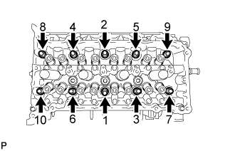 |
Using a 10 mm bi-hexagon wrench, install and uniformly tighten the 10 cylinder head bolts in several steps, in the sequence shown in the illustration.
Step 2:
Tighten the cylinder head bolts again in the sequence shown in the illustration to make sure that they are tightened to the specified torque.
Step 3:
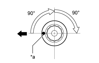 |
Mark each cylinder head bolt head with paint as shown in the illustration.
| *a | Paint Mark |
| Front |
Tighten the cylinder head bolts by 90° in the sequence shown in step 1.
Step 4:
Tighten the cylinder head bolts by another 90° in the sequence shown in step 1.
Check that the paint marks are now facing rearward.
| 13. SET CAMSHAFT TIMING GEAR ASSEMBLY |
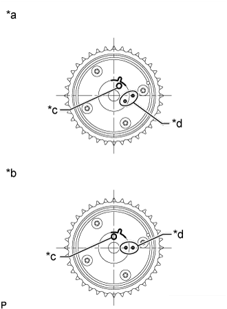 |
Check the camshaft timing gear assembly position.
| *a | Advanced Position |
| *b | Retarded Position |
| *c | Knock Pin Hole |
| *d | Alignment Mark |
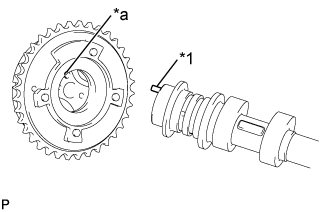 |
Align and insert the knock pin of the camshaft with the pin hole of the camshaft timing gear assembly.
| *1 | Knock Pin |
| *a | Pin Hole |
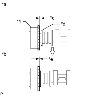 |
Check that there is no clearance between the camshaft timing gear assembly and camshaft flange.
| *1 | Camshaft Timing Gear Assembly |
| *a | Incorrect |
| *b | Correct |
| *c | Clearance |
| *d | Camshaft Flange |
| *e | No Clearance |
Secure the camshaft in place by hand, and then install the installation bolt of the camshaft timing gear assembly by hand.
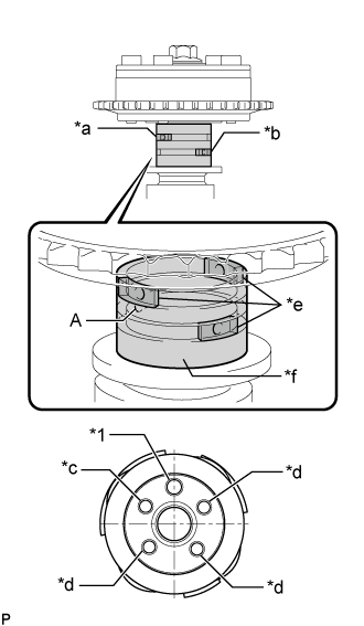 |
Release the lock pin.
| *1 | Knock Pin |
| *a | Retard Side Path |
| *b | Advance Side Path |
| *c | Open |
| *d | Close |
| *e | Rubber |
| *f | Vinyl Tape |
Clean the camshaft journal with non-residue solvent.
Cover the 4 oil paths of the camshaft journal with vinyl tape as shown in the illustration.
Open a hole at port (A) shown in the illustration.
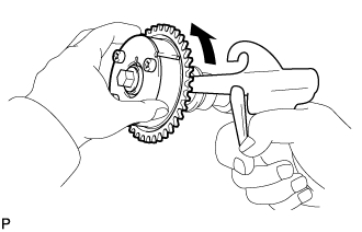 |
While applying approximately 200 kPa (2.0 kgf/ cm2, 29 psi) of air pressure to the oil path, forcibly turn the camshaft timing gear assembly in the advance direction (counterclockwise).
Remove the vinyl tape and rubber pieces from the camshaft.
Remove the bolt and camshaft timing gear assembly.
| 14. INSTALL CAMSHAFT BEARING CAP SETTING RING PIN |
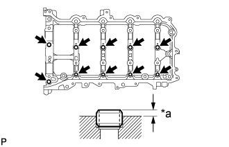 |
Using a plastic-faced hammer, tap in 10 new ring pins to the camshaft housing.
| *a | Protrusion Height |
| 15. INSTALL CAMSHAFT HOUSING STRAIGHT PIN |
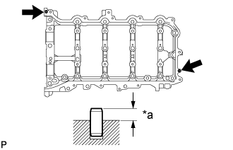 |
Using a plastic-faced hammer, tap in 2 new straight pins to the camshaft housing.
| *a | Protrusion Height |
| 16. INSTALL CAMSHAFT HOUSING STUD BOLT |
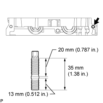 |
Using an E8 "TORX" socket wrench, install the stud bolt.
| 17. INSTALL NO. 1 CAMSHAFT BEARING |
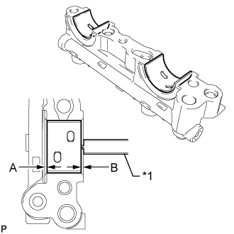 |
Clean the No. 1 camshaft bearing.
| *1 | Vernier Caliper |
Install the camshaft bearing to the No. 1 camshaft bearing cap.
Using a vernier caliper, measure the distance between the camshaft bearing cap edge and the camshaft bearing edge.
| 18. INSTALL NO. 2 CAMSHAFT BEARING |
Clean the No. 2 camshaft bearing.
Install the camshaft bearing to the camshaft housing.
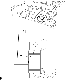 |
Using a vernier caliper, measure the distance between the camshaft housing edge and the camshaft bearing edge.
| *1 | Vernier Caliper |
| 19. INSTALL OIL CONTROL VALVE FILTER |
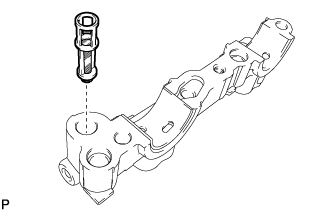 |
Install the oil control valve filter to the No. 1 camshaft bearing cap.
| 20. INSTALL CAMSHAFT |
Clean the camshaft journals, camshaft housing sub-assembly and camshaft bearing caps.
Apply a light coat of engine oil to the camshaft journal, camshaft housing sub-assembly and camshaft bearing caps.
Install the camshaft and No. 2 camshaft to the camshaft housing sub-assembly.
| 21. INSTALL CAMSHAFT BEARING CAP |
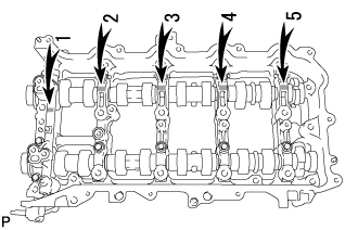 |
Confirm the marks and numbers on the No. 1 camshaft bearing cap, No. 2 camshaft bearing cap and 3 No. 3 camshaft bearing caps and place them in their proper positions and directions.
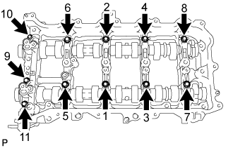 |
Install the 11 bolts in the order shown in the illustration.
| 22. INSTALL VALVE STEM CAP |
Apply a light coat of engine oil to the valve stem ends.
Install the 16 valve stem caps to the cylinder head sub-assembly.
| 23. INSTALL VALVE LASH ADJUSTER ASSEMBLY |
Inspect the valve lash adjuster assemblies before installing them .
Install the 16 valve lash adjuster assemblies to the cylinder head sub-assembly.
| 24. INSTALL NO. 1 VALVE ROCKER ARM SUB-ASSEMBLY |
Apply engine oil to the valve lash adjuster assembly tips and valve stem caps.
Install the 16 No. 1 valve rocker arm sub-assemblies as shown in the illustration.
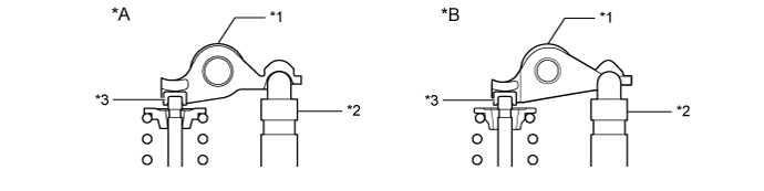
| *A | Type A | *B | Type B |
| *1 | No. 1 Valve Rocker Arm Sub-assembly | *2 | Valve Lash Adjuster Assembly |
| *3 | Valve Stem Cap | - | - |
| 25. INSTALL CAMSHAFT HOUSING SUB-ASSEMBLY |
Check that the No. 1 valve rocker arm sub-assemblies are installed as shown in the illustration.
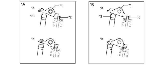
| *A | Type A | *B | Type B |
| *1 | No. 1 Valve Rocker Arm Sub-assembly | *2 | Valve Stem Cap |
| *3 | Valve Lash Adjuster Assembly | - | - |
| *a | INCORRECT | *b | CORRECT |
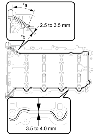 |
Apply seal packing in a continuous line as shown in the illustration.
| *a | Dashed Line |
| *b | Groove |
| Area | Seal Packing Diameter | Application Position |
| Continuous Line | 3.0 to 4.0 mm (0.118 to 0.157 in.) | Distance from edge of camshaft housing sub-assembly to center of seal packing: 3.5 to 4.0 mm (0.138 to 0.157 in.) |
| Dashed Line | Distance from outside edge of groove to center of seal packing: 2.5 to 3.5 mm (0.0984 to 0.138 in.) |
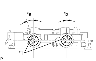 |
Position the knock pins of the camshaft and No. 2 camshaft as shown in the illustration.
| *1 | Knock Pin |
| *a | Approximately 17° |
| *b | Approximately 2° |
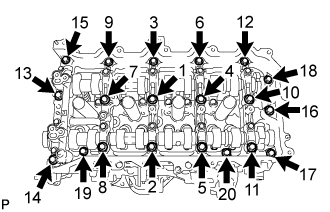 |
Install the camshaft housing sub-assembly, and then install the 20 bolts in the order shown in the illustration.
| 26. INSTALL CAMSHAFT TIMING GEAR ASSEMBLY |
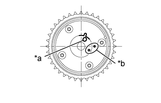 |
Check the camshaft timing gear assembly position.
| *a | Knock Pin Hole |
| *b | Alignment Mark |
|
Align and insert the knock pin of the camshaft with the pin hole of the camshaft timing gear assembly.
| *1 | Knock Pin |
| *a | Pin Hole |
|
Check that there is no clearance between the camshaft timing gear assembly and camshaft flange.
| *1 | Camshaft Timing Gear Assembly |
| *a | Incorrect |
| *b | Correct |
| *c | Clearance |
| *d | Camshaft Flange |
| *e | No Clearance |
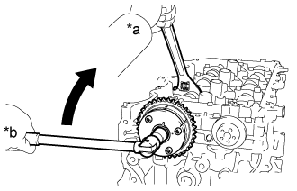 |
Using a wrench to hold the hexagonal portion of the camshaft, install the bolt.
| *a | Hold |
| *b | Turn |
| 27. INSTALL CAMSHAFT TIMING EXHAUST GEAR ASSEMBLY |
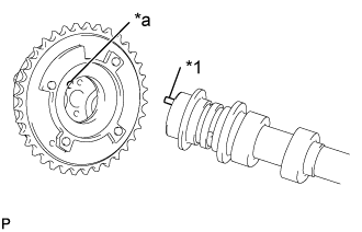 |
Align and insert the knock pin of the No. 2 camshaft with the pin hole of the camshaft timing exhaust gear assembly.
| *1 | Knock Pin |
| *a | Pin Hole |
|
Check that there is no clearance between the camshaft timing exhaust gear assembly and No. 2 camshaft flange.
| *1 | Camshaft Timing Exhaust Gear Assembly |
| *a | Incorrect |
| *b | Correct |
| *c | Clearance |
| *d | No. 2 Camshaft Flange |
| *e | No Clearance |
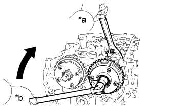 |
Using a wrench to hold the hexagonal portion of the No. 2 camshaft, install the bolt.
| *a | Hold |
| *b | Turn |
| 28. INSTALL CRANKSHAFT TIMING SPROCKET |
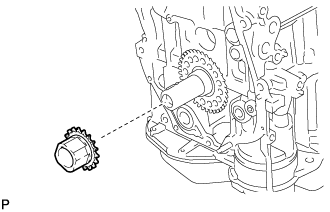 |
Install the crankshaft timing sprocket to the crankshaft.
| 29. ADD ENGINE OIL |
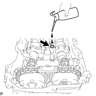 |
Add 50 cc (3.1 cu. in.) of engine oil into the oil hole shown in the illustration.
| 30. SET NO. 1 CYLINDER TO TDC/COMPRESSION |
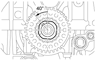 |
Temporarily install the crankshaft pulley bolt.
Rotate the crankshaft 40° counterclockwise to position the crankshaft pulley key as shown in the illustration.
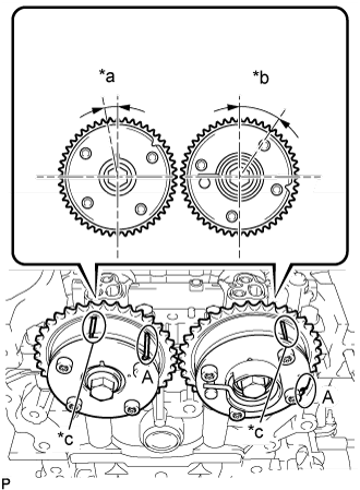 |
Check that the timing marks of the camshaft timing exhaust gear assembly and camshaft timing gear assembly are as shown in the illustration.
| *a | Approximately 7° |
| *b | Approximately 32° |
| *c | Timing Mark |
| 31. INSTALL NO. 1 CHAIN VIBRATION DAMPER |
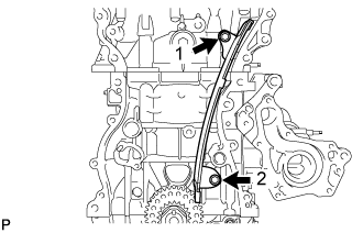 |
Install the No. 1 chain vibration damper with the 2 bolts in the order shown in the illustration.
| 32. INSTALL CHAIN SUB-ASSEMBLY |
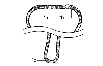 |
| *a | for Intake Side |
| *b | for Exhaust Side |
| *c | for Crankshaft |
| Type of Chain Sub-assembly | for Exhaust Side | for Intake Side | for Crankshaft |
| Type A | Yellow | Yellow | Pink |
| Type B | Gold | Gold | Gold |
| Type C | Orange | Orange | Yellow |
Place the chain sub-assembly onto the camshaft timing exhaust gear assembly, camshaft timing gear assembly and crankshaft timing sprocket.
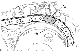 |
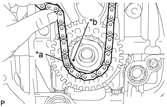
Align the mark plate (for Exhaust Side) of the chain sub-assembly with the timing mark of the camshaft timing exhaust gear assembly and install the chain sub-assembly to the camshaft timing exhaust gear assembly.
| *a | Mark Plate (for Exhaust Side) |
| *b | Timing Mark |
 |
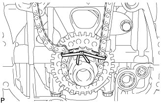
Align the mark plate (for Crankshaft) of the chain sub-assembly with the timing mark of the crankshaft timing sprocket and install the chain sub-assembly to the crankshaft timing sprocket.
| *a | Mark Plate (for Crankshaft) |
| *b | Timing Mark |
 |
Tie a string above the crankshaft timing sprocket so that the chain sub-assembly is secure.
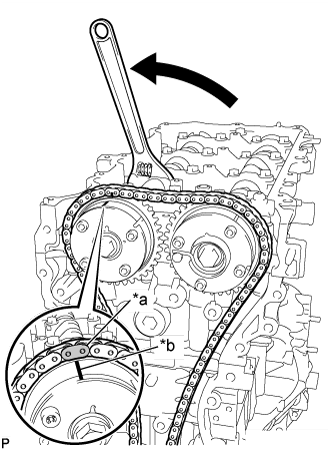 |
Using the hexagonal portion of the camshaft, rotate the camshaft counterclockwise with a wrench, align the timing mark of the camshaft timing gear assembly with the mark plate (for Intake Side) of the chain sub-assembly and install the chain sub-assembly to the camshaft timing gear assembly.
| *a | Mark Plate (for Intake Side) |
| *b | Timing Mark |
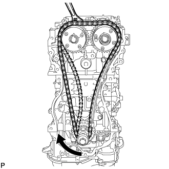 |
Remove the string above the crankshaft timing sprocket, rotate the crankshaft clockwise, and loosen the chain sub-assembly so that the chain tensioner slipper can be installed.
| 33. INSTALL CHAIN TENSIONER SLIPPER |
Install the chain tensioner slipper with the bolt.
| 34. INSTALL NO. 1 CHAIN TENSIONER ASSEMBLY |
Install a new gasket and the No. 1 chain tensioner assembly with the 2 bolts.
Remove the pin from the stopper plate.
| 35. INSTALL TIMING CHAIN GUIDE |
Install the timing chain guide with the bolt.
| 36. SET NO. 1 CYLINDER TO TDC/COMPRESSION |
Temporarily install the crankshaft pulley bolt.
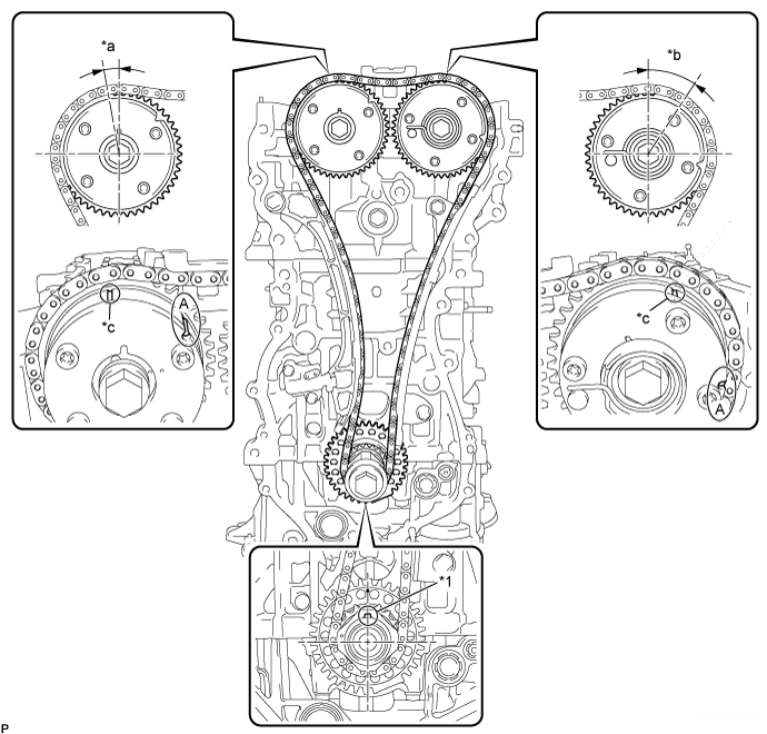
| *1 | Crankshaft Pulley Key | - | - |
| *a | Approximately 7° | *b | Approximately 32° |
| *c | Timing Mark | - | - |
Rotate the crankshaft clockwise and align the crankshaft pulley key as shown in the illustration.
Check that the timing marks on the camshaft timing exhaust gear assembly and camshaft timing gear assembly are as shown in the illustration
Remove the crankshaft pulley bolt.
| 37. INSTALL TIMING CHAIN COVER PLATE |
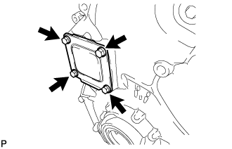 |
Install a new gasket and the timing chain cover plate with the 4 bolts.
| 38. INSTALL TIMING CHAIN COVER TIGHT PLUG |
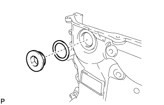 |
Using a 14 mm hexagon wrench, install a new gasket and the plug.
| 39. INSTALL TIMING CHAIN COVER SUB-ASSEMBLY |
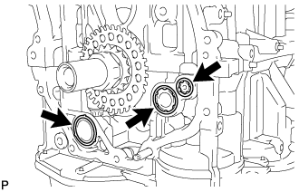 |
Apply a light coat of engine oil to 2 new oil pump gaskets and a new oil hole cover gasket.
Install the 2 oil pump gaskets and oil hole cover gasket to the stiffening crankcase assembly.
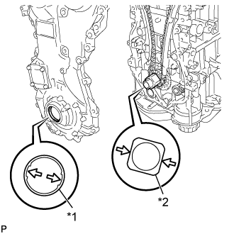 |
Align the drive rotor spline and crankshaft timing sprocket as shown in the illustration.
| *1 | Drive Rotor Spline |
| *2 | Crankshaft Timing Sprocket |
Apply seal packing in a line to the timing chain cover sub-assembly as shown in the following illustration.
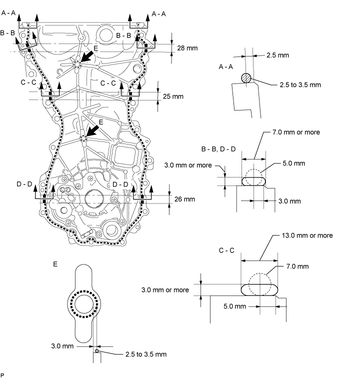
| Area | Seal Packing Diameter (Round) | Distance from Edge of Cover to Center of Seal Packing | Seal Packing Application Length |
| Seal Packing Dimension (Flat) | |||
| Dashed Line | 2.5 to 3.5 mm (0.0984 to 0.138 in.) | 2.5 mm (0.0984 in.) | - |
| - | |||
| A - A | 2.5 to 3.5 mm (0.0984 to 0.138 in.) | 2.5 mm (0.0984 in.) | - |
| - | |||
| B - B | 5.0 mm (0.197 in.) | 3.0 mm (0.118 in.) | 28 mm (1.10 in.) |
| 7.0 mm (0.276 in.) or wider and 3.0 mm (0.118 in.) or thicker | |||
| C - C | 7.0 mm (0.276 in.) | 5.0 mm (0.197 in.) | 25 mm (0.984 in.) |
| 13.0 mm (0.512 in.) or wider and 3.0 mm (0.118 in.) or thicker | |||
| D - D | 5.0 mm (0.197 in.) | 3.0 mm (0.118 in.) | 26 mm (1.02 in.) |
| 7.0 mm (0.276 in.) or wider and 3.0 mm (0.118 in.) or thicker | |||
| E | 2.5 to 3.5 mm (0.0984 to 0.138 in.) | 3.0 mm (0.118 in.) | - |
| - |
Temporarily install the timing chain cover sub-assembly with the 17 bolts and 2 nuts.
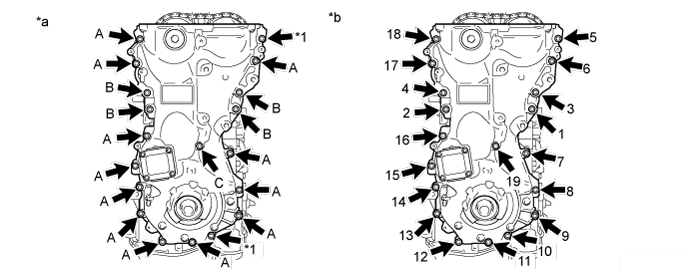
| *1 | Nut | - | - |
| *a | Torque | *b | Tightening Order |
| Item | Length | Thread Diameter |
| Bolt A | 30 mm (1.18 in.) | 8 mm (0.315 in.) |
| Bolt B | 35 mm (1.38 in.) | 10 mm (0.394 in.) |
| Bolt C | 45 mm (1.77 in.) | 8 mm (0.315 in.) |
Tighten the 17 bolts and 2 nuts in several steps, in the sequence shown in the illustration.
| 40. INSTALL ENGINE MOUNTING BRACKET RH |
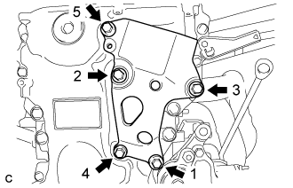 |
Install the engine mounting bracket RH with the 5 bolts in the order shown in the illustration.
| 41. INSTALL TIMING CHAIN COVER OIL SEAL |
Apply MP grease to the lip of a new oil seal.
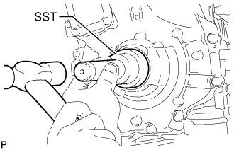 |
Using SST and a hammer, tap in the oil seal until its surface is flush with the timing chain cover edge.
| 42. INSTALL SPARK PLUG TUBE GASKET |
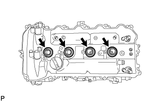 |
Install 4 new plug tube gaskets to the cylinder head cover.
| 43. INSTALL CYLINDER HEAD COVER SUB-ASSEMBLY |
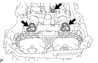 |
Apply a light coat of engine oil to 3 new gaskets.
Install the 3 gaskets to the camshaft bearing caps.
Install a new gasket to the cylinder head cover.
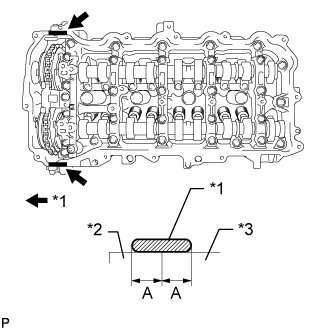 |
Apply seal packing as shown in the illustration.
| *1 | Seal Packing |
| *2 | Timing Chain Cover |
| *3 | Camshaft Housing |
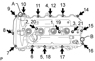 |
Align the cylinder head cover with pin A. Then align the cylinder head cover with pin B and install the cylinder head cover.
Install 3 new seal washers and the 16 bolts, and then tighten the bolts in the order shown in the illustration.
| 44. INSTALL CRANKSHAFT PULLEY |
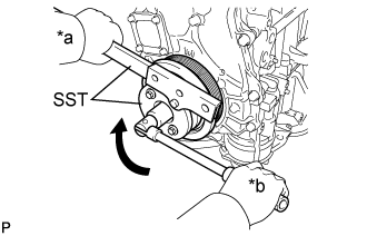 |
Align the pulley set key with the key groove of the crankshaft pulley.
| *a | Hold |
| *b | Turn |
Using SST, hold the crankshaft pulley and install the pulley bolt.
| 45. INSTALL CRANKSHAFT POSITION SENSOR |
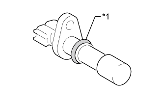 |
Apply a light coat of engine oil to the O-ring of the crankshaft position sensor.
| *1 | O-ring |
Install the crankshaft position sensor with the bolt.
Connect the crankshaft position sensor connector.
| 46. INSTALL WATER INLET HOUSING |
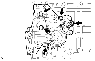 |
Install a new gasket and the inlet water housing with the 4 bolts and nut.
| 47. INSTALL ENGINE WATER PUMP ASSEMBLY |
Install a new gasket and the engine water pump with the 7 bolts.
| 48. INSTALL V-RIBBED BELT TENSIONER ASSEMBLY |
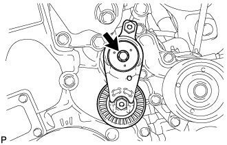 |
Install the V-ribbed belt tensioner with the bolt.
| 49. INSTALL THERMOSTAT |
Install a new gasket to the thermostat.
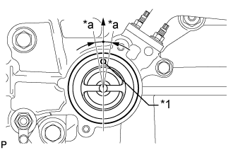 |
Install the thermostat with the jiggle valve facing upward.
| *1 | Jiggle valve |
| *a | 10° |
| 50. INSTALL WATER INLET |
Install the water inlet with the 2 nuts.
| 51. INSTALL NO. 1 WATER BY-PASS PIPE |
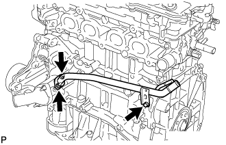 |
Install a new gasket and the water by-pass pipe with the 2 nuts and bolt.
| 52. INSTALL SEPARATOR CASE |
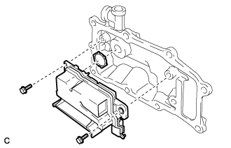 |
Apply a light coat of engine oil to a new gasket.
Install the gasket to the separator case.
Install the separator case with the 2 bolts.
| 53. INSTALL VENTILATION CASE SUB-ASSEMBLY |
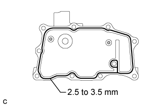 |
Apply seal packing in a continuous line as shown in the illustration.
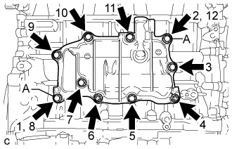 |
Install the ventilation case, and install the 8 bolts and 2 nuts in the order shown in the illustration.
| 54. INSTALL VENTILATION VALVE SUB-ASSEMBLY |
Apply adhesive to 2 or 3 threads of the ventilation valve sub-assembly.
Using a 19 mm deep socket wrench, install the ventilation valve sub-assembly.
Connect the No. 2 ventilation hose to the ventilation valve sub-assembly.
| 55. INSTALL CAMSHAFT POSITION SENSOR (for Intake Side) |
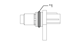 |
Apply a light coat of engine oil to the O-ring of the camshaft position sensor.
| *1 | O-ring |
Install the camshaft position sensor with the bolt.
Connect the camshaft position sensor connector.
| 56. INSTALL CAMSHAFT POSITION SENSOR (for Exhaust Side) |
|
Apply a light coat of engine oil to the O-ring of the camshaft position sensor.
| *1 | O-ring |
Install the camshaft position sensor with the bolt.
Connect the camshaft position sensor connector.
| 57. INSTALL CAMSHAFT TIMING OIL CONTROL VALVE ASSEMBLY |
Camshaft timing oil control valve assembly (for exhaust side)
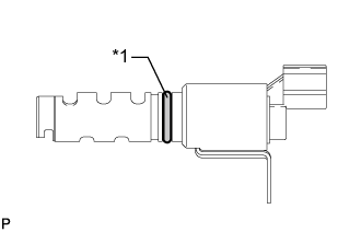 |
Apply a light coat of engine oil to a new O-ring, and install it to the oil control valve.
| *1 | New O-ring |
Install the oil control valve with the bolt.
Connect the oil control valve connector.
Camshaft timing oil control valve assembly (for intake side)
|
Apply a light coat of engine oil to a new O-ring, and install it to the oil control valve.
| *1 | New O-ring |
Install the oil control valve with the bolt.
Connect the oil control valve connector.
| 58. INSTALL OIL FILLER CAP SUB-ASSEMBLY |
Install a new gasket to the oil filler cap.
Install the oil filler cap to the cylinder head.
| 59. INSTALL SPARK PLUG |
Using a spark plug wrench, install the 4 spark plugs.
| 60. INSTALL ENGINE COVER JOINT |
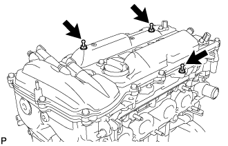 |
Install the 3 joints.