 |
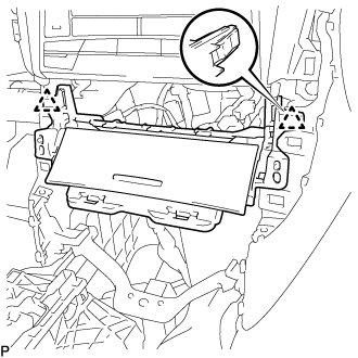
Engage the 2 clips.
CLEARANCE WARNING BUZZER > INSTALLATION |
| 1. INSTALL NO. 1 CLEARANCE WARNING BUZZER |
Engage the clamp to install the No. 1 clearance warning buzzer.
Connect the connector.
| 2. INSTALL FRONT ASH RECEPTACLE ASSEMBLY |
Connect each connector.
|
Engage the 2 clips.
Install the front ash receptacle assembly with the 2 screws <D>.
| 3. INSTALL FRONT CONSOLE UPPER PANEL GARNISH |
for Blank Type:
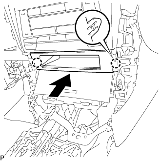 |
Engage the 2 claws to install the front console upper panel garnish as shown in the illustration.
for 3 Switch Hole Type:
Connect each connector.
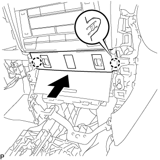 |
Engage the 2 claws to install the front console upper panel garnish as shown in the illustration.
| 4. INSTALL REAR CONSOLE UPPER PANEL SUB-ASSEMBLY |
Connect each connector.
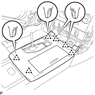 |
Engage the 6 clips to install the rear console upper panel sub-assembly.
Move the shift lever to P.
| 5. INSTALL SHIFT LEVER KNOB SUB-ASSEMBLY |
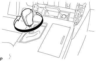 |
Turn the shift lever knob sub-assembly clockwise to install it.
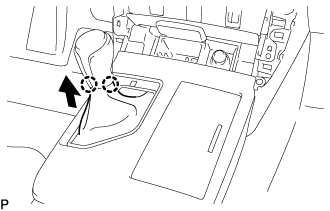 |
Engage the 2 claws to connect the shift hole cover sub-assembly as shown in the illustration.
| 6. INSTALL FRONT PANEL GARNISH LH |
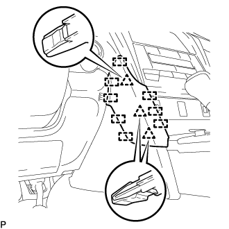 |
Engage the 3 clips and 8 guides to install the front panel garnish LH.
| 7. INSTALL FRONT PANEL GARNISH RH |
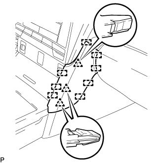 |
Engage the 3 clips and 8 guides to install the front panel garnish RH.