FRONT LOWER SUSPENSION ARM (for 6AR-FSE) > INSTALLATION |
| 1. INSTALL FRONT LOWER NO. 1 SUSPENSION ARM SUB-ASSEMBLY LH (for LH Side) |
Install the front lower arm bushing stopper to the front lower No. 1 suspension arm sub-assembly LH.
![]() |
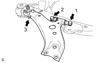
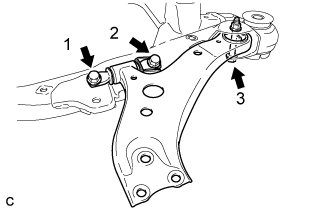
Install the front lower No. 1 suspension arm sub-assembly LH to the front frame assembly with the 3 bolts and nut in the order shown in the illustration.
Install the front lower No. 1 suspension arm sub-assembly LH to the front lower ball joint assembly with the bolt and 2 nuts.
| 2. INSTALL ENGINE MOUNTING INSULATOR LH (for LH Side) |
![]() |
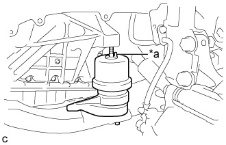
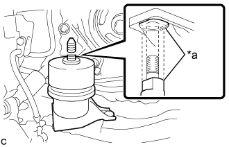
Set the engine mounting insulator LH on the front frame assembly.
| *a | Pin |
Slowly lower the engine assembly with transaxle using a jack and a wooden block.
![]() |
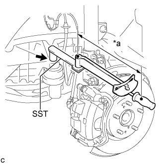
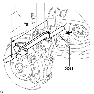
Using SST, install the nut to the engine mounting insulator LH.
| *a | Torque Wrench Fulcrum Length |
![]() |
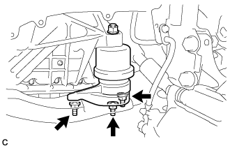
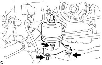
Install the engine mounting insulator LH with the 3 nuts.
Install the 2 hole plugs.
| 3. INSTALL FRONT LOWER NO. 1 SUSPENSION ARM SUB-ASSEMBLY RH (for RH Side) |
Install the front lower arm bushing stopper to the front lower No. 1 suspension arm sub-assembly RH.
![]() |
Install the front lower No. 1 suspension arm sub-assembly RH to the front frame assembly with the 3 bolts and nut in the order shown in the illustration.
Install the front lower No. 1 suspension arm sub-assembly RH to the front lower ball joint assembly with the bolt and 2 nuts.
| 4. INSTALL ENGINE MOUNTING INSULATOR RH (for RH Side) |
![]() |
Set the engine mounting insulator RH on the front frame assembly.
| *a | Cutout |
Slowly lower the engine assembly with transaxle using a jack and a wooden block.
![]() |
Using SST, install the nut to the engine mounting insulator RH.
| *a | Torque Wrench Fulcrum Length |
![]() |
Install the engine mounting insulator RH with the 3 nuts.
Install the 2 hole plugs.
| 5. INSTALL ENGINE MOVING CONTROL ROD BRACKET (for RH Side) |
![]() |
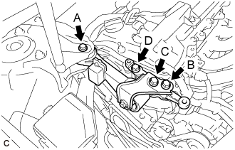
Temporarily install the engine moving control rod bracket with the 4 bolts.
Fully tighten the engine moving control rod bracket with the 4 bolts.
| 6. INSTALL NO. 2 ENGINE MOUNTING STAY RH (for RH Side) |
Install the No. 2 engine mounting stay RH with the 2 bolts.
| 7. INSTALL EARTH WIRE (for RH Side) |
Install the earth wire with the bolt.
| 8. INSTALL FRONT ENGINE MOUNTING INSULATOR |
Install the front engine mounting insulator to the front frame assembly with the 3 nuts.
| 9. INSTALL HEATED OXYGEN SENSOR |
Connect the heated oxygen sensor connector.
| 10. INSTALL FRONT FENDER APRON SEAL LH (for LH Side) |
Install the front fender apron seal LH with the 2 bolts and clip.
| 11. INSTALL FRONT FENDER APRON SEAL RH (for RH Side) |
Install the front fender apron seal RH with the 2 bolts and clip.
| 12. INSTALL ENGINE UNDER COVER LH |
Install the engine under cover LH with the 3 screws and 2 clips.
| 13. INSTALL FRONT WHEEL OPENING EXTENSION PAD LH |
Install the front wheel opening extension pad LH with the 3 screws.
| 14. INSTALL ENGINE UNDER COVER RH |
Install the engine under cover RH with the 3 screws and 3 clips.
| 15. INSTALL FRONT WHEEL OPENING EXTENSION PAD RH |
Install the front wheel opening extension pad RH with the 3 screws.
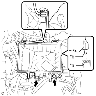
| 16. INSTALL AIR CLEANER CASE SUB-ASSEMBLY |
![]() |
Insert the projection of the air cleaner case sub-assembly into the hole of the No. 1 air cleaner bracket as shown in the illustration.
| *a | Hole |
| *b | Projection |
Install the 2 bolts.
Connect the wire harness clamp.
| 17. INSTALL AIR CLEANER FILTER ELEMENT SUB-ASSEMBLY |
Install the air cleaner filter element sub-assembly to the air cleaner case sub-assembly.
| 18. INSTALL AIR CLEANER CAP WITH AIR CLEANER HOSE |
Connect the air cleaner cap with air cleaner hose to the throttle body with motor assembly.
Install the air cleaner cap with air cleaner hose with the 2 guides and 2 air cleaner cap clamps.
Tighten the hose clamp.
Connect the union to connector tube hose to the air cleaner hose sub-assembly.
Engage the wire harness clamp.
Connect the mass air flow meter sub-assembly connector.
Engage the ventilation hose clamp.
Connect the ventilation hose to the cylinder head cover sub-assembly and slide the clip to secure it.
| 19. INSTALL NO. 1 ENGINE COVER SUB-ASSEMBLY |
Engage the 3 grommets to install the No. 1 engine cover sub-assembly.
| 20. INSTALL FRONT OUTER COWL TOP PANEL SUB-ASSEMBLY |
Install the front outer cowl top panel sub-assembly with the 10 bolts.
Engage the 2 clamps to install the wire harness to the front outer cowl top panel sub-assembly.
w/ Windshield Deicer System:
Connect the connector.
Engage the 2 clamps to install the wire harness to the front outer cowl top panel sub-assembly.
w/ Heated Windshield Defroster System:
Connect the 2 connectors.
Engage the 4 clamps to install the wire harness to the front outer cowl top panel sub-assembly.
| 21. INSTALL WINDSHIELD WIPER MOTOR AND LINK ASSEMBLY |
| 22. INSTALL FRONT WHEELS |
| 23. CONNECT CABLE TO NEGATIVE BATTERY TERMINAL |
| 24. INSPECT AND ADJUST FRONT WHEEL ALIGNMENT |