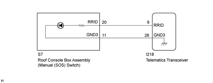
TELEMATICS SYSTEM > Emergency Call Switch Illumination Circuit |
| 1.INSPECT ROOF CONSOLE BOX ASSEMBLY (MANUAL (SOS) SWITCH) |
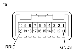 |
Remove the roof console box assembly (manual (SOS) switch) (Click here).
Connect 4 dry-cell batteries (1.5 V each) in series.
Connect a positive (+) from the batteries lead to terminal 20 (RRID) and a negative (-) lead to terminal 11 (GND3) of the roof console box assembly (manual (SOS) switch) connector.
Check if the manual (SOS) switch illuminates.
| *a | Component without harness connected (Roof Console Box Assembly (Manual (SOS) Switch) |
|
| ||||
| OK | |
 |
| 2.CHECK HARNESS AND CONNECTOR (TELEMATICS TRANSCEIVER - ROOF CONSOLE BOX ASSEMBLY) |
Disconnect the I218 telematics transceiver connector.
Disconnect the S7 roof console box assembly (manual (SOS) switch) connector.
Measure the resistance according to the value(s) in the table below.
| Tester Connection | Condition | Specified Condition |
| I218-9 (SLID) - S7-20 (RRID) | Always | Below 1 Ω |
| I218-26 (GND3) - S7-11 (GND3) | Always | Below 1 Ω |
| I218-9 (SLID) or S7-20 (RRID) - Body ground | Always | 10 kΩ or higher |
| I218-26 (GND3) or S7-11 (GND3) - Body ground | Always | 10 kΩ or higher |
|
| ||||
| OK | ||
 | ||
| ||
