BODY PANEL FIT STANDARD / ADJUSTMENT METHOD ADJUSTMENT
Refer to the TOYOTA Repair Manual for adjustment method.
- HINT:
-
Vehicle Exterior
INSPECT HOOD SUB-ASSEMBLY
Check that the clearance measurements of areas a through f are within each standard range.
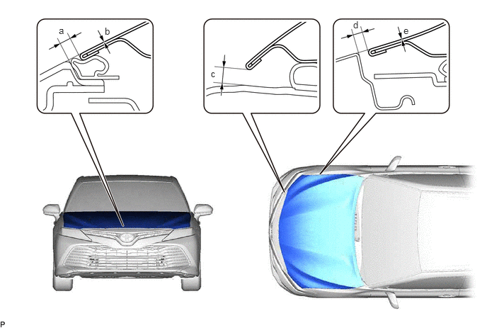
| Area | Measurement | Area | Measurement |
|---|---|---|---|
| a | 2.8 to 6.8 mm (0.110 to 0.268 in.) | b | -2 to 2 mm (-0.0787 to 0.0787 in.) |
| c | 5.9 to 9.9 mm (0.232 to 0.390 in.) | d | 2.5 to 5.5 mm (0.0984 to 0.217 in.) |
| e | -1.5 to 1.5 mm (-0.0591 to 0.0591 in.) | - | - |
- HINT:
-
Centering bolts are used to install the hood hinges and hood lock. The hood and hood lock cannot be adjusted with the centering bolts installed. Substitute the centering bolts with standard bolts with washers when making adjustments.
INSPECT FRONT DOOR
Check that the clearance measurements of areas a through n are within each standard range.
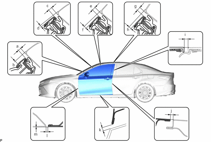
| Area | Measurement | Area | Measurement |
|---|---|---|---|
| a | 3.3 to 6.7 mm (0.130 to 0.264 in.) | b | 3.5 to 7.5 mm (0.138 to 0.295 in.) |
| c | 3.3 to 6.7 mm (0.130 to 0.264 in.) | d | 0.2 to 4.2 mm (0.0079 to 0.165 in.) |
| e | 3.3 to 6.7 mm (0.130 to 0.264 in.) | f | 1.2 to 5.2 mm (0.0472 to 0.205 in.) |
| g | 3.3 to 6.7 mm (0.130 to 0.264 in.) | h | 1.1 to 5.1 mm (0.0433 to 0.201 in.) |
| i | 2.3 to 6.3 mm (0.0906 to 0.248 in.) | j | 4.1 mm (0.161 in.) |
| k | 5.3 mm (0.209 in.) | l | 2.6 to 5.0 mm (0.102 to 0.197 in.) |
| m | -1.2 to 1.2 mm (-0.0472 to 0.0472 in.) | - | - |
- HINT:
- ·
Use the same procedure for the RH side and LH side.
·The following procedure is for the LH side.
·Centering bolts are used to install the door hinges to the vehicle body and door. The door cannot be adjusted with the centering bolts installed. Substitute the centering bolts with standard bolts when making adjustments.
INSPECT REAR DOOR
Check that the clearance measurements of areas a through o are within each standard range.
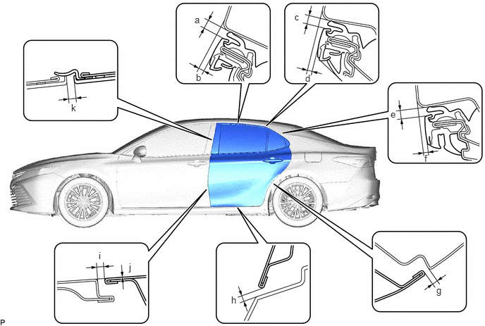
| Area | Measurement | Area | Measurement |
|---|---|---|---|
| a | 3.3 to 6.7 mm (0.130 to 0.264 in.) | b | 1.2 to 5.2 mm (0.0472 to 0.205 in.) |
| c | 3.3 to 6.7 mm (0.130 to 0.264 in.) | d | 0.6 to 4.6 mm (0.0236 to 0.181 in.) |
| e | 3.3 to 6.7 mm (0.130 to 0.264 in.) | f | 0.6 to 4.6 mm (0.0236 to 0.181 in.) |
| g | 2.3 to 5.3 mm (0.0906 to 0.209 in.) | h | 5.3 mm (0.209 in.) |
| i | 4.1 mm (0.161 in.) | j | 0 mm (0 in.) |
| k | 2.3 to 6.3 mm (0.0906 to 0.248 in.) | - | - |
- HINT:
- ·
Use the same procedure for the RH side and LH side.
·The following procedure is for the LH side.
·Centering bolts are used to install the door hinges to the vehicle body and door. The door cannot be adjusted with the centering bolts installed. Substitute the centering bolts with standard bolts when making adjustments.
INSPECT BACK DOOR
Check that the clearance measurements of areas a through l are within each standard range.
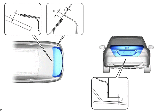
| Area | Measurement | Area | Measurement |
|---|---|---|---|
| a | 5.8 mm (0.228 in.) | b | 2.6 to 5.6 mm (0.102 to 0.220 in.) |
| c | -1.4 to 1.6 mm (-0.0551 to 0.063 in.) | d | 4.0 to 8.0 mm (0.157 to 0.315 in.) |
- HINT:
-
Centering bolts are used to install the door hinges to the door. The door cannot be adjusted with the centering bolts installed. Substitute the centering bolts with standard bolts (with washers) when making adjustments.