NM33A0E
_51
Engine / Hybrid System
_067336
A25A-FKS ENGINE MECHANICAL
_0328392
ENGINE UNIT
DE
DETAILS
F
A25A-FKS ENGINE MECHANICAL ENGINE UNIT DETAILS BLOWBY GAS VENTILATION CONTROL
CONSTRUCTION
a.
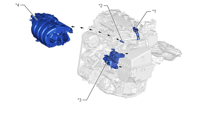
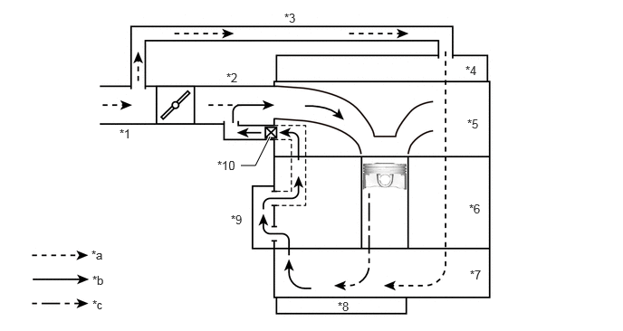
By using a PCV system which directly intakes blowby gas from the crankcase to the No. 1 ventilation case, ventilation efficiency has been enhanced and oil deterioration is reduced.
b.
A Labyrinth structure is used for the oil mist separator of the No. 1 ventilation case. By enhancing the oil mist collection rate, oil consumption and the buildup of deposits have been decreased.
c.
By integrating the PCV valve into the cylinder head, the vacuum hose has been discontinued and the PCV system has been simplified.
2.74,3.344 2.875,3.344
2.875,3.344 3.563,2.042
true
4.49,0.958 4.875,0.385
4.875,0.385 5.01,0.385
true
3.438,0.188 3.563,0.188
3.563,0.188 4.052,1.375
true
0.677,0.167 0.802,0.167
0.802,0.167 1.24,0.677
true
5.052,0.292 5.365,0.448
0.313,0.156
10
false
*1
3.271,0.104 3.583,0.26
0.313,0.156
10
false
*2
2.573,3.26 2.885,3.417
0.313,0.156
10
false
*3
0.51,0.083 0.823,0.24
0.313,0.156
10
false
*4
| *1 | No. 2 Ventilation Hose | *2 | PCV Valve |
| *3 | No. 1 Ventilation Case | *4 | Intake Manifold |
PCV Passage Diagram
2.771,1.906 2.938,1.906
2.938,1.906 3.104,1.573
true
1.375,1.458 1.594,1.635
0.219,0.177
10
false
*1
2.604,0.813 2.813,0.979
0.208,0.167
10
false
*2
3.271,0.125 3.469,0.302
0.198,0.177
10
false
*3
5.354,0.729 5.563,0.885
0.208,0.156
10
false
*4
5.375,1.344 5.573,1.521
0.198,0.177
10
false
*5
5.396,2.323 5.604,2.5
0.208,0.177
10
false
*6
5.406,3.083 5.615,3.26
0.208,0.177
10
false
*7
3.885,3.448 4.094,3.604
0.208,0.156
10
false
*8
2.656,2.448 2.865,2.615
0.208,0.167
10
false
*9
2.5,1.823 2.771,1.99
0.271,0.167
10
false
*10
1.052,2.854 1.271,3.063
0.219,0.208
10
false
*a
1.063,3.146 1.26,3.313
0.198,0.167
10
false
*b
1.063,3.427 1.26,3.635
0.198,0.208
10
false
*c
| *1 | No. 1 Air Cleaner Hose | *2 | Intake Manifold |
| *3 | No. 2 Ventilation Hose | *4 | Cylinder Head Cover Sub-assembly |
| *5 | Cylinder Head Sub-assembly | *6 | Cylinder Block Sub-assembly |
| *7 | Stiffening Crankcase Assembly | *8 | No. 2 Oil Pan Sub-assembly |
| *9 | No. 1 Ventilation Case | *10 | PCV Valve |
| *a | Fresh Air | *b | Blowby Gas + Fresh Air |
| *c | Blowby Gas | - | - |