6AR-FSE EMISSION CONTROL EMISSION CONTROL SYSTEM CONTROL BLOWBY GAS VENTILATION CONTROL
FUNCTION OF MAIN COMPONENTS
The main components of the blowby gas ventilation system are as follows:
| Component | Function |
|---|---|
| PCV Valve | Opens and closes using vacuum generated in the intake manifold and controls the flow rate of the blowby gas. |
| Oil Separator (Ventilation Case Sub-assembly) | Collects oil mist in the blowby gas, reducing the oil consumption. |
| Oil Pre-separator (No. 1 Ventilation Case) | Separates the engine oil from the blowby gas. |
SYSTEM CONTROL
By introducing blowby gas that has a large amount of HC into the intake manifold for combustion, the system prevents the blowby gas, which includes a large amount of HC, from being discharged into the atmosphere. The amount of airflow through the crankcase (blowby gas introduction volume) is controlled according to the engine operating conditions. This prevents the excessive consumption of engine oil, and is a factor in idle speed control.
This system uses the ventilation method, which sucks the blowby gas directly from the stiffening crankcase assembly, enhancing the ventilation efficiency.
An oil separator (ventilation case sub-assembly) is provided in the blowby gas passage inside the cylinder head cover sub-assembly. This separates the engine oil from the blowby gas in order to reduce oil degradation and reduce the amount of engine oil consumed.
An oil pre-separator (No. 1 ventilation case) is provided in the cylinder block assembly, improving the separation of oil from the blowby gas.
The Positive Crankcase Ventilation (PCV) valve passage returns the blowby gas into the intake manifold in accordance with the intake manifold vacuum.
Under light load conditions, the intake manifold vacuum causes the blowby gas to be drawn via the PCV valve into the intake manifold.
Under high load conditions, the introduction of fresh air is stopped, allowing a large amount of blowby gas to be drawn into the intake system.
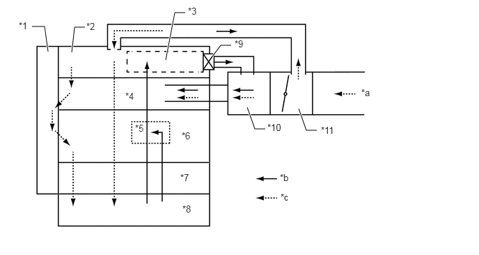
| *1 | Timing Chain Cover Assembly | *2 | Cylinder Head Cover Sub-assembly |
| *3 | Oil Separator (Ventilation Case Sub-assembly) | *4 | Cylinder Head Sub-assembly |
| *5 | Oil Pre-separator (No. 1 Ventilation Case) | *6 | Cylinder Block Sub-assembly |
| *7 | Stiffening Crankcase Assembly | *8 | Oil Pan Sub-assembly |
| *9 | PCV Valve | *10 | Intake Manifold |
| *11 | Throttle Body with Motor Assembly | - | - |
| *a | from Air Cleaner Assembly | *b | Blowby Gas |
| *c | Fresh Air | - | - |