M20A-FKS ENGINE MECHANICAL ENGINE UNIT DETAILS PISTON
CONSTRUCTION
The pistons are made of aluminum alloy to allow them to be compact and lightweight.
A piston with a concave top surface is used to prevent air turbulence and to achieve high speed combustion. This contributes to the prevention of engine knock which enables a high compression ratio, resulting in increased performance and reduced fuel consumption.
The casting process and the structure of the piston have been optimized, achieving thinner inner walls and resulting in a drastic weight reduction.
The skirt portion of the piston has a resin coating to ensure a smooth surface. By minimizing bore friction, protection against scuffing is enhanced. Also, the surface of the skirt portion of the piston has a laser-cut crosshatch microgroove for enhanced oil retention.
A Physical Vapor Deposition (PVD) coating have been applied to the surface of the No. 1 compression ring, in order to improve wear resistance.
A Diamond Like Carbon (DLC) coating has been applied to the surface of the oil ring side rail, in order to reduce friction losses and improve wear resistance.
The groove of the No. 1 compression ring is coated with alumite to ensure abrasion resistance.
To counteract increased oil consumption at high RPM, the circumference of the oil ring side rail adopts an asymmetrical barrel shape. In addition to greatly reduced oil consumption, decreased friction is realized due to optimization of oil ring tension.
An oil ring expander which utilizes punched grooves to prevent deposits from accumulating is used. Oil flow between the expander and side rails is enhanced, achieving a structure that prevents deposits from accumulating.
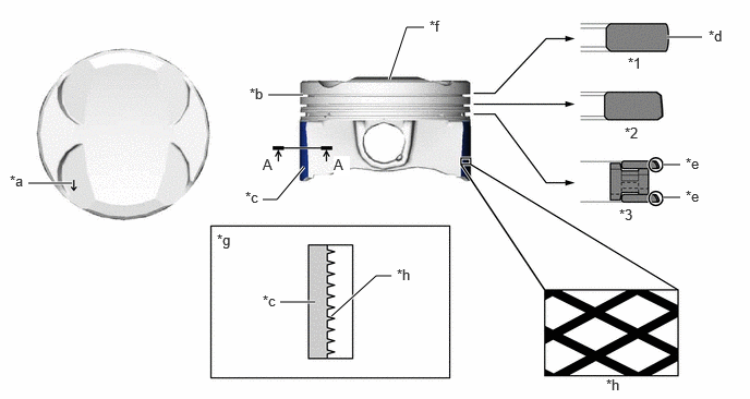
| *1 | No. 1 Compression Ring | *2 | No. 2 Compression Ring |
| *3 | Oil Ring | - | - |
| *a | Front Mark | *b | Alumite Coating |
| *c | Resin Coating | *d | PVD Coating |
| *e | DLC Coating | *f | Combustion Bowl |
| *g | A-A Cross Section | *h | Cross Hatch |
By tilting the sidewalls of the piston towards the piston center, the combustion pressure is better distributed to the piston pin. This allows for higher power output capability.
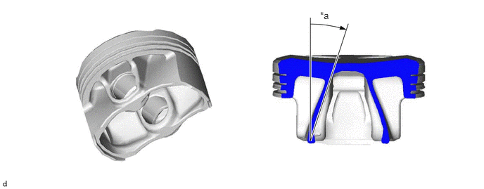
| *a | Tilted Sidewall | - | - |