M20A-FKS COOLING COOLANT FLOW CONTROL VARIABLE COOLING CONTROL
FUNCTION OF MAIN COMPONENTS
| Component | Function | |
|---|---|---|
| Flow Shutting Valve (Water Valve) | Selects a coolant passage based on signals from the ECM. | |
| Engine Water Pump Assembly (Water Inlet Housing) | Optimizes coolant circulation based on signals from the ECM. | |
| Water Inlet with Thermostat Sub-assembly | Thermostat with Heater | Assists opening the thermostat with heater valve based on signals from the ECM. |
| Engine Coolant Temperature Sensor | Detects the engine coolant temperature. | |
| Crank Position Sensor | Detects the engine speed. | |
| ECM | Changed the flow shutting valves (water valves) by the engine conditions. | |
FUNCTION
By using the variable cooling system that consists of the thermostat with heater, engine water pump assembly (water inlet housing) and flow shutting valve (water valve), engine warm-up capability has been enhanced, friction has been reduced and low fuel consumption has been achieved.
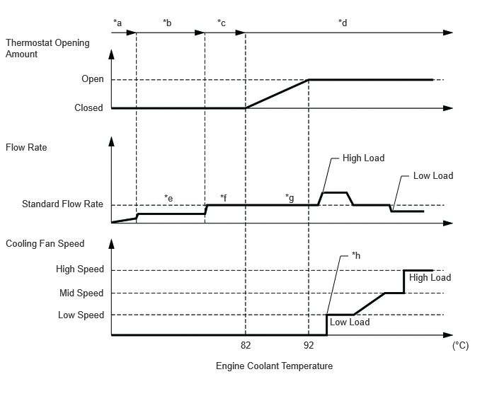
| *a | Coolant Flow Stopped (Startup Calibration) | *b | Restricted Flow Rate Control |
| *c | Standard Flow Rate Control | *d | Combustion Chamber Wall Temperature Control |
| *e | Flow Rate to Minimize Piston Slap | *f | Flow Rate Resulting in a 10°C Difference in Coolant Temperature Between Inlet and Outlet of Engine |
| *g | The standard flow rate is Increased or decreased depending on engine load after thermostat open. | *h | Depending on the control conditions, the starting temperature of the cooling fan varies. |
Early Warm-up
The flow rate is reduced to minimize piston slap during warm up.
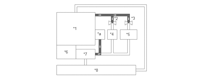
| *1 | Engine | *2 | Flow Shutting Valve (Water Valve) (for Heater Control) (Closed) |
| *3 | Flow Shutting Valve (Water Valve) (for CVT Fluid Control) (Closed) | *4 | Heater Radiator Unit Sub-assembly |
| *5 | CVT Fluid Warmer (Transmission Oil Cooler) | *6 | Engine Water Pump Assembly (Water Inlet Housing) |
| *7 | Water Inlet with Thermostat Sub-assembly
·
Thermostat with Heater |
*8 | Radiator Assembly |
| *a | EGR Cooler Assembly, etc. | - | - |
Heater Priority
Engine coolant flows only through the heater radiator unit sub-assembly to increase heating performance.
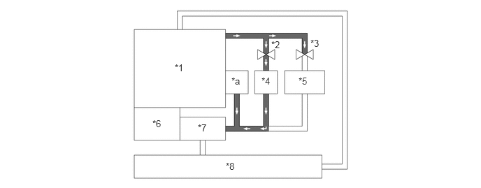
| *1 | Engine | *2 | Flow Shutting Valve (Water Valve) (for Heater Control) (Open) |
| *3 | Flow Shutting Valve (Water Valve) (for CVT Fluid Control) (Closed) | *4 | Heater Radiator Unit Sub-assembly |
| *5 | CVT Fluid Warmer (Transmission Oil Cooler) | *6 | Engine Water Pump Assembly (Water Inlet Housing) |
| *7 | Water Inlet with Thermostat Sub-assembly
·
Thermostat with Heater |
*8 | Radiator Assembly |
| *a | EGR Cooler Assembly, etc. | - | - |
Output Enhancement
When current is not applied to the thermostat with heater, coolant flow volume is increased, enhancing output. Additionally, applying current to the thermostat with heater decreases thermostat with heater opening temperature, ensuring cooler efficiency.
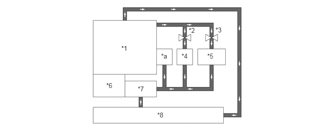
| *1 | Engine | *2 | Flow Shutting Valve (Water Valve) (for Heater Control) (Open) |
| *3 | Flow Shutting Valve (Water Valve) (for CVT Fluid Control) (Open) | *4 | Heater Radiator Unit Sub-assembly |
| *5 | CVT Fluid Warmer (Transmission Oil Cooler) | *6 | Engine Water Pump Assembly (Water Inlet Housing) |
| *7 | Water Inlet with Thermostat Sub-assembly
·
Thermostat with Heater |
*8 | Radiator Assembly |
| *a | EGR Cooler Assembly, etc. | - | - |
MAX Cool
The flow of engine coolant to the heater radiator unit sub-assembly is stopped in order to improve the cooling efficiency of the air conditioning system.
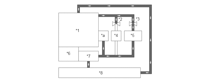
| *1 | Engine | *2 | Flow Shutting Valve (Water Valve) (for Heater Control) (Closed) |
| *3 | Flow Shutting Valve (Water Valve) (for CVT Fluid Control) (Open) | *4 | Heater Radiator Unit Sub-assembly |
| *5 | CVT Fluid Warmer (Transmission Oil Cooler) | *6 | Engine Water Pump Assembly (Water Inlet Housing) |
| *7 | Water Inlet with Thermostat Sub-assembly
·
Thermostat with Heater |
*8 | Radiator Assembly |
| *a | EGR Cooler Assembly, etc. | - | - |