NM33A0E
_52
Drivetrain
_065981
UB80E AUTOMATIC TRANSMISSION / TRANSAXLE
_0328981
AUTOMATIC TRANSAXLE SYSTEM
DE
DETAILS
F
UB80E AUTOMATIC TRANSMISSION / TRANSAXLE AUTOMATIC TRANSAXLE SYSTEM DETAILS SHIFT CONTROL
CONSTRUCTION
a.
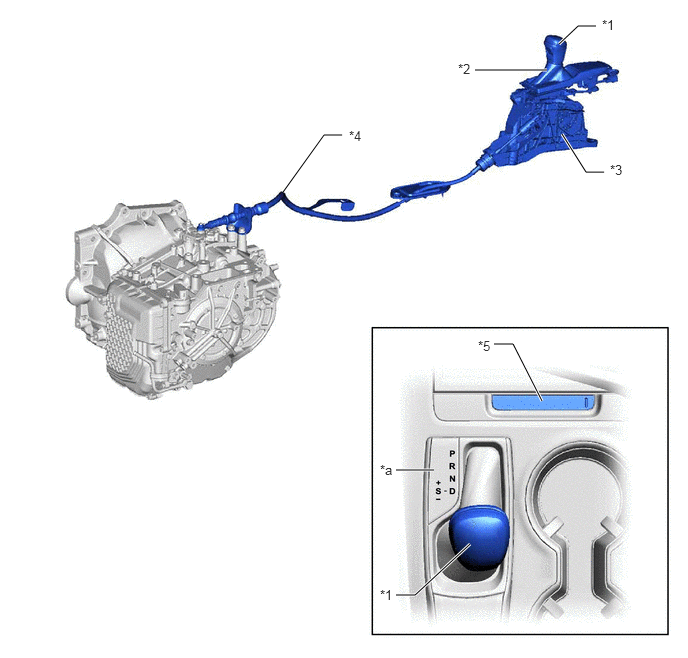
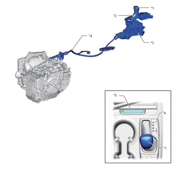
A straight type shift lever with boot that uses a transmission control cable assembly is used.
b.
The shift control mechanism consists of a transmission floor shift assembly, a shift lever knob sub-assembly and a transmission control cable assembly.
c.
A shift lock release button is provided inside the shift lever housing in consideration of emergency situations. A cover is provided on the shift lock release button to prevent erroneous operation.
LHD Models
4.948,0.729 5.698,0.729
true
5.823,0.458 6.021,0.271
6.021,0.271 6.208,0.271
true
5.854,1.396 6.104,1.792
6.104,1.792 6.292,1.792
true
2.948,2 3.375,1.406
3.375,1.406 3.563,1.406
true
5.146,3.583 5.344,3.583
5.344,3.583 5.646,4.177
true
4.125,6.198 4.323,6.198
4.323,6.198 4.896,5.667
true
4.125,4.896 4.521,4.896
true
6.271,0.177 6.583,0.333
0.313,0.156
10
false
*1
4.771,0.635 5.083,0.792
0.313,0.156
10
false
*2
6.354,1.688 6.667,1.844
0.313,0.156
10
false
*3
3.635,1.333 3.948,1.49
0.313,0.156
10
false
*4
4.979,3.521 5.292,3.677
0.313,0.156
10
false
*5
3.958,6.115 4.271,6.271
0.313,0.156
10
false
*1
3.958,4.813 4.167,5.083
0.208,0.271
10
false
*a
| *1 | Shift Lever Knob Sub-assembly | *2 | Shift Lever Boot |
| *3 | Transmission Floor Shift Assembly | *4 | Transmission Control Cable Assembly |
| *5 | Shift Lock Release Button Cover | - | - |
| *a | Shift Pattern | - | - |
RHD Models
4.823,0.625 5.458,0.625
true
5.625,1.333 5.875,1.729
5.875,1.729 6.063,1.729
true
2.927,2.042 3.354,1.448
3.354,1.448 3.542,1.448
true
4.844,3.885 5.042,3.885
5.042,3.885 5.344,4.479
true
6.333,5 6.5,4.583
6.5,4.583 6.583,4.583
true
5.615,0.313 6.073,0.313
true
6,5.75 6.5,6
6.5,6 6.583,6
true
6.146,0.25 6.51,0.583
0.365,0.333
10
false
*1
4.615,0.552 5.094,0.885
0.479,0.333
10
false
*2
6.135,1.656 6.49,1.969
0.354,0.313
10
false
*3
3.615,1.375 3.979,1.667
0.365,0.292
10
false
*4
4.625,3.781 5.042,4.104
0.417,0.323
10
false
*5
6.656,5.927 7.073,6.5
0.417,0.573
10
false
*1
6.625,4.49 6.875,4.906
0.25,0.417
10
false
*a
| *1 | Shift Lever Knob Sub-assembly | *2 | Shift Lever Boot |
| *3 | Transmission Floor Shift Assembly | *4 | Transmission Control Cable Assembly |
| *5 | Shift Lock Release Button Cover | - | - |
| *a | Shift Pattern | - | - |
d.
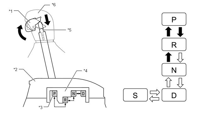
The shift lever used is a 5-position (P, R, N, D and S) straight type lever. Along with the change to a straight-type lever, a detent mechanism using shift lever knob button operation was added to prevent accidentally shifting from P to R, R to P, or N to R.
Detent Mechanism (Image)
0.458,0.354 0.604,0.354
0.604,0.354 1,0.76
true
0.625,2.313 0.771,2.313
0.771,2.313 1.167,2.719
true
1.448,3.573 1.594,3.573
1.594,3.573 1.76,3.177
true
2.156,3.052 2.542,2.365
2.542,2.365 2.719,2.365
true
1.26,0.438 1.479,0.167
1.479,0.167 1.656,0.167
true
1.396,1 2.188,1
true
0.292,0.292 0.625,0.583
0.333,0.292
10
false
*1
0.448,2.24 0.76,2.396
0.313,0.156
10
false
*2
1.281,3.51 1.594,3.667
0.313,0.156
10
false
*3
2.771,2.281 3.083,2.438
0.313,0.156
10
false
*4
2.24,0.917 2.552,1.073
0.313,0.156
10
false
*5
1.719,0.073 2.031,0.229
0.313,0.156
10
false
*6
| *1 | Shift Lever Knob button | *2 | Transmission Floor Shift Assembly |
| *3 | Detent Plate | *4 | Detent |
| *5 | Detent Rod | *6 | Shift Lever Knob Sub-assembly |

|
Shift Lever knob button operation necessary | 
|
Shift Lever knob button operation not necessary |