Home › Vehicle Exterior › EXTERIOR PANELS / TRIM › BODY STRUCTURE › from 2021.02
NM33A0E _59 Vehicle Exterior _068184 EXTERIOR PANELS / TRIM _0332942 BODY STRUCTURE DE DETAILS F

EXTERIOR PANELS / TRIM  BODY STRUCTURE  DETAILS  BODY SHELL  


CONSTRUCTION


a.

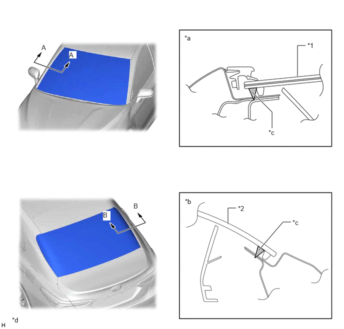
High-rigidity Urethane Sealant

i.

A high-rigidity urethane sealant is used to adhere the windshield and back door glass to the vehicle to improve body rigidity and ensure excellent driving stability.
Y214461C05
5.667,2.667 5.667,2.333 5.667,2.333 5.25,1.917 true 6.198,1.615 6.198,0.948 6.198,0.948 6.365,0.948 true 4.75,4.667 4.75,4.333 4.75,4.333 4.917,4.333 true 5.396,5.208 5.896,4.625 5.896,4.625 6.063,4.625 true 6.406,0.865 6.719,1.021 0.313,0.156 10 false *1 4.958,4.26 5.271,4.417 0.313,0.156 10 false *2 3.844,0.708 4.156,0.865 0.313,0.156 10 false *a 3.854,4.115 4.167,4.271 0.313,0.156 10 false *b 5.594,2.677 5.906,2.833 0.313,0.156 10 false *c 0.865,0.906 1.021,1.063 0.156,0.156 10 true A 1.438,1.063 1.594,1.219 0.156,0.156 10 true A 2.146,4.396 2.302,4.594 0.156,0.198 10 true B 2.781,4.208 2.938,4.406 0.156,0.198 10 true B 6.094,4.552 6.406,4.708 0.313,0.156 10 false *c 0.25,6.583 0.563,6.74 0.313,0.156 10 false *d
*1 Windshield *2 Back Door Glass
*a A - A Cross Section *b B - B Cross Section
*c High-rigidity Urethane Sealant *d The illustrations shown are examples only.


b.

Upper Body

i.

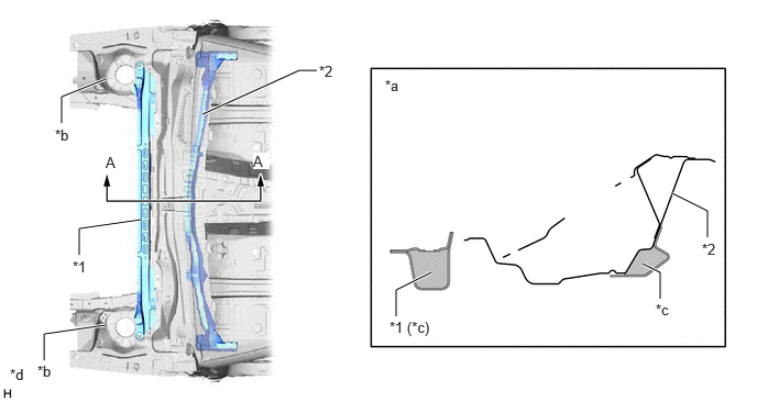
The cowl that connects the front suspension towers employs a circular structure.


ii.

Thus suspension tower rigidity in the vertical and horizontal directions has been enhanced.
Y214458C05
0.583,1.167 0.583,0.917 0.583,0.917 1,0.75 true 0.417,3.417 0.417,3.167 0.417,3.167 1,3.083 true 0.75,2.417 0.75,2.167 0.75,2.167 1.333,2.083 true 1.917,1.083 2.833,0.667 2.833,0.667 3,0.667 true 3.75,3 3.75,2.75 3.75,2.75 4.083,2.583 true 6.25,2.833 6.25,2.583 6.25,2.583 6.083,2.5 true 6.698,2.25 6.698,2 6.698,2 6.365,1.833 true 0.688,2.448 1,2.604 0.313,0.156 10 false *1 6.646,2.281 6.958,2.438 0.313,0.156 10 false *2 3.646,0.729 3.958,0.885 0.313,0.156 10 false *a 1,1.458 1.156,1.615 0.156,0.156 10 true A 0.521,1.198 0.833,1.354 0.313,0.156 10 false *b 3.688,3.021 4.323,3.25 0.635,0.229 10 false *1 (*c) 2.396,1.448 2.552,1.604 0.156,0.156 10 true A 0.354,3.438 0.667,3.594 0.313,0.156 10 false *b 3.021,0.594 3.333,0.75 0.313,0.156 10 false *2 6.208,2.854 6.521,3.01 0.313,0.156 10 false *c 0.094,3.469 0.406,3.625 0.313,0.156 10 false *d
*1 Front Suspension Brace Sub-assembly Upper Center *2 Cowl Top Panel
*a A - A Cross Section *b Suspension Tower
*c Close Section *d The illustrations shown are examples only.


iii.

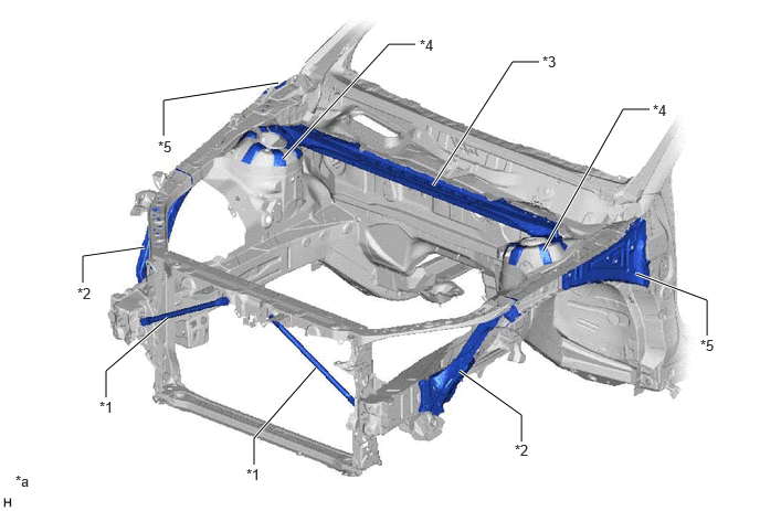
Excellent body rigidity are achieved by the following structure.

·

Radiator support brace "V" configuration.

·

Outer riggers are provided.

·

Suspension tower brace is provided.

·

Strengthen suspension tower aprons.

·

Strengthen apron upper members.

Y214474C04
1,3.75 1,3.5 1,3.5 1.583,3 true 2.396,4.385 2.396,4.135 2.396,4.135 2.979,3.469 true 0.781,2.667 0.781,2.417 0.781,2.417 1.365,2.333 true 4.917,4.167 4.917,3.917 4.917,3.917 4.333,3.5 true 4.083,1.75 4.833,0.583 4.833,0.583 5.083,0.583 true 5.125,2.365 5.875,1.031 5.875,1.031 6.125,1.031 true 2.667,1.5 3.667,0.417 3.667,0.417 3.917,0.417 true 1.542,1.281 1.542,0.948 1.542,0.948 2.625,0.781 true 6.667,3.167 6.667,2.833 6.667,2.833 6,2.583 true 0.938,3.76 1.25,3.917 0.313,0.156 10 false *1 0.729,2.688 1.042,2.844 0.313,0.156 10 false *2 5.115,0.5 5.427,0.656 0.313,0.156 10 false *3 3.958,0.344 4.271,0.5 0.313,0.156 10 false *4 1.49,1.302 1.802,1.458 0.313,0.156 10 false *5 2.323,4.396 2.635,4.552 0.313,0.156 10 false *1 4.854,4.167 5.167,4.323 0.313,0.156 10 false *2 6.156,0.958 6.469,1.115 0.313,0.156 10 false *4 6.604,3.177 6.917,3.333 0.313,0.156 10 false *5 0.146,4.458 0.458,4.615 0.313,0.156 10 false *a
*1 Radiator Support Brace *2 Outer Rigger
*3 Suspension Tower Brace *4 Suspension Tower Aprons
*5 Apron Upper Member - -
*a The illustrations shown are examples only. - -


iv.

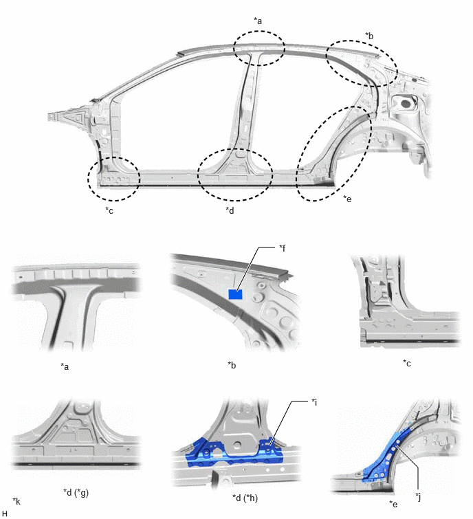
The door openings in the body have a circular structure.
Y214460C05
3.583,4.417 3.917,3.75 3.917,3.75 4.167,3.75 true 4.083,6.75 4.417,6.083 4.417,6.083 4.667,6.083 true 6.333,7.417 6.333,7.083 6.333,7.083 6,6.75 true 3.844,0.229 4.156,0.385 0.313,0.156 10 false *a 5.531,0.458 5.844,0.615 0.313,0.156 10 false *b 1.594,3.104 1.906,3.26 0.313,0.156 10 false *c 3.417,3.104 3.729,3.26 0.313,0.156 10 false *d 5.198,2.927 5.51,3.083 0.313,0.156 10 false *e 4.229,3.677 4.542,3.833 0.313,0.156 10 false *f 4.719,6.01 4.875,6.167 0.156,0.156 10 false *i 6.292,7.438 6.479,7.677 0.188,0.24 10 false *j 0.917,5.469 1.229,5.625 0.313,0.156 10 false *a 3.448,5.448 3.76,5.604 0.313,0.156 10 false *b 6.104,5.417 6.417,5.573 0.313,0.156 10 false *c 0.958,7.375 1.406,7.615 0.448,0.24 10 false *d (*g) 3.521,7.458 3.969,7.698 0.448,0.24 10 false *d (*h) 5.896,7.552 6.208,7.708 0.313,0.156 10 false *e 0.188,7.51 0.521,7.677 0.333,0.167 10 false *k
*a Center pillar and rail coupling area *b Rear rail coupling area
*c Front pillar and rocker coupling area *d Center pillar and rocker coupling area
*e Rocker rear end structure *f Advanced body adhesive
*g Outer side *h Cabin side
*i Gusset *j Rocker Panel Reinforcement
*k The illustrations shown are examples only. - -


v.

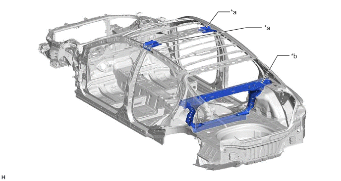
Roof coupling rigidity is improved (*a)


vi.

The rear back panel a circular structure to ensure ample rigidity. (*b)
Y214459E01
4.333,0.583 4.583,0.25 4.583,0.25 4.833,0.25 true 5.5,1.75 5.833,1.167 5.833,1.167 6.083,1.167 true 3.333,0.917 5.167,0.583 5.167,0.583 5.5,0.583 true 4.844,0.167 5.302,0.365 0.458,0.198 10 false *a 5.552,0.5 6.01,0.698 0.458,0.198 10 false *a 6.115,1.094 6.427,1.292 0.313,0.198 10 false *b

The illustrations shown are examples only.


vii.

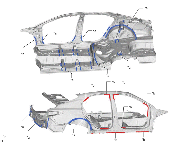
Innovative fastening methods such as laser screw welding and advanced body adhesives creates a more rigid chassis, which translates into a car that is more fun, more agile and better to drive.
Y212602C04
4.76,3.844 4.76,3.344 4.76,3.344 4.927,3.344 true 5.99,4.302 5.99,3.802 5.99,3.802 6.156,3.802 true 4.333,3.833 4.333,3.333 4.333,3.333 4.5,3.333 true 3.5,4.052 3.5,3.469 3.5,3.469 3.667,3.469 true 3,5.417 3,5.25 3,5.25 3.417,4.833 true 1.135,5.521 1.135,5.354 1.135,5.354 1.469,5.021 true 5.167,1.083 5.667,0.333 5.667,0.333 5.833,0.333 true 1.719,1.677 1.969,1.344 1.969,1.344 2.135,1.344 true 3.333,1.583 3.583,1.25 3.583,1.25 3.75,1.25 true 0.938,2.104 0.938,1.938 0.938,1.938 1.438,1.604 true 2.917,3.167 2.917,3 2.917,3 2.667,2.833 true 4.385,3 4.385,2.833 4.385,2.833 3.969,2.583 true 5.25,2.667 5.25,2.5 5.25,2.5 4.833,2.25 true 0.896,5.083 0.896,4.917 0.896,4.917 1.229,4.583 true 4.708,5.406 4.708,5.615 true 5.833,5.396 5.833,5.604 true 4.979,5.198 5.031,4.354 5.031,4.354 5.198,4.354 true 0.865,2.115 1.177,2.313 0.313,0.198 10 false *a 2.177,1.271 2.49,1.469 0.313,0.198 10 false *a 3.792,1.177 4.104,1.375 0.313,0.198 10 false *a 5.885,0.24 6.198,0.438 0.313,0.198 10 false *a 2.865,3.177 3.177,3.375 0.313,0.198 10 false *a 4.323,3 4.635,3.198 0.313,0.198 10 false *a 5.188,2.667 5.5,2.865 0.313,0.198 10 false *a 1.083,5.521 1.396,5.719 0.313,0.198 10 false *a 0.844,5.094 1.156,5.292 0.313,0.198 10 false *a 2.938,5.427 3.25,5.625 0.313,0.198 10 false *a 3.719,3.396 4.031,3.594 0.313,0.198 10 false *b 4.542,3.26 4.854,3.458 0.313,0.198 10 false *b 4.979,3.271 5.292,3.469 0.313,0.198 10 false *b 6.188,3.719 6.5,3.917 0.313,0.198 10 false *b 5.24,4.281 5.552,4.479 0.313,0.198 10 false *b 4.646,5.615 4.958,5.813 0.313,0.198 10 false *b 5.771,5.615 6.083,5.813 0.313,0.198 10 false *b 0.125,5.49 0.438,5.688 0.313,0.198 10 false *c
*a Advanced body adhesive *b Laser screw welding
*c The illustrations shown are examples only. - -


c.

Front Seat Attachment Part

i.

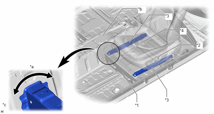
The following structure ensures the rigidity of the front seat attachment part.

·

Height of the floor tunnel to higher.

·

Adopted continuous flange for No. 1 seat cross member.

·

Optimize seat rear bracket shape.

·

Attached the seat rail directly to the body.
Y214475C07
4.583,3.417 4.583,3.167 4.583,3.167 4.083,2.417 true 6.5,1.5 6,1.5 6,1.5 5.25,1.917 true 5.583,3.25 5.583,3 5.583,3 5.083,2.25 true 6,1 5.5,1 5.5,1 4.75,1.417 true 5.5,0.5 5,0.5 5,0.5 4.333,1.417 true 4.594,0.292 4.094,0.292 4.094,0.292 3.427,1.208 true 4.521,3.438 4.833,3.594 0.313,0.156 10 false *1 6.583,1.427 6.792,1.635 0.208,0.208 10 true *2 5.521,3.26 5.833,3.417 0.313,0.156 10 true *3 6.021,0.938 6.25,1.156 0.229,0.219 10 true *4 1,2.146 1.313,2.302 0.313,0.156 10 true *a 5.531,0.448 5.771,0.667 0.24,0.219 10 true *3 4.625,0.219 4.885,0.438 0.26,0.219 10 true *b 0.083,3.417 0.396,3.573 0.313,0.156 10 false *c
*1 No.1 Seat Cross Member *2 No. 2 Seat Cross Member
*3 Seat Rail *4 Seat Rear Bracket
*a Continuous Flange *b Floor Tunnel
*c The illustrations shown are examples only. - -


d.

Rear Suspension Member

i.

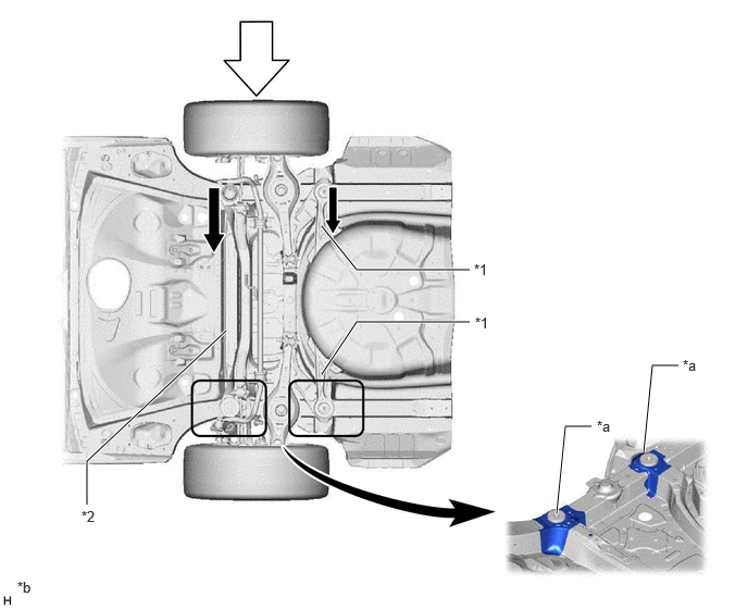
The lateral rigidity is secured by the following structure.

·

A rear suspension member braces are provided.

·

An under body cross member is provided.

·

Optimized rear cross member attachment.
Y214476C05
3.083,2.167 3.417,2.583 3.417,2.583 4.5,2.583 true 3.083,3.583 3.417,3.083 3.417,3.083 4.5,3.083 true 0.833,4.833 0.833,4.417 0.833,4.417 2.167,3.167 true 5.333,4.917 5.417,4.083 5.417,4.083 5.667,4.083 true 6.167,4.333 6.25,3.5 6.25,3.5 6.5,3.5 true 4.542,2.5 4.854,2.698 0.313,0.198 10 false *1 4.552,3.01 4.865,3.208 0.313,0.198 10 false *1 0.781,4.865 1.094,5.063 0.313,0.198 10 false *2 5.719,4 6.031,4.198 0.313,0.198 10 false *a 6.542,3.417 6.854,3.615 0.313,0.198 10 false *a 0.167,5.542 0.479,5.74 0.313,0.198 10 false *b
*1 Rear Suspension Member Brace *2 Under Body Cross Member
*a Rear Cross Member Attachment *b The illustrations shown are examples only.
V100136

Lateral Force from Tire
V100135

Dissipate