NAVIGATION / MULTI INFO DISPLAY NAVIGATION SYSTEM CONTROL AUDIO CONTROL
FUNCTION OF MAIN COMPONENTS
| Component | Function | |
|---|---|---|
|
*1: w/ Telematics Transceiver *2: w/o Telematics Transceiver *3: w/ Headup Display System *4: w/ DAB Function *5: w/ DTV Function *6: w/ Cooler Control Switch Assembly *7: w/ Stereo Component Amplifier Assembly *8: w/o Stereo Component Amplifier Assembly |
||
| Radio and Display Receiver Assembly | ·
Outputs the audio signal of the selected audio source to the stereo component amplifier assembly.*7 ·
Outputs the audio signal of the selected audio source to the speakers.*8 ·
Sends each sound source and hands-free system status to the combination meter assembly. ·
Receives navigation information, etc. image and audio signals and operation status via direct line from the navigation ECU or USB communication. ·
Based on the image signal sent from the navigation ECU, displays the map screen, operation screen, etc. ·
Sends the operation signals input via the capacitive touch display panel the navigation ECU. |
|
| Navigation ECU | ·
Contains the navigation ECU, gyro sensor, GPS signal receiver and storage device, manages the radio and operation signals received from the radio and display receiver assembly, and controls the navigation system. ·
Sends navigation information, etc. image and sound signals and the operation status to the radio and display receiver assembly. |
|
| Major Components of Navigation ECU | Navigation Computer | ·
Corrects the vehicle location based on location information calculated from the GPS information, vehicle speed signal, information from equipped sensors and the shift status. ·
Using the calculated vehicle location mark and map database, sends the information and operation status to the radio and display receiver assembly. ·
Sends the audio signals such as voice guidance provided based on the vehicle location to the radio and display receiver assembly. ·
Sends the voice guidance audio signal to the radio and display receiver assembly. ·
Sends navigation information such as the vehicle direction and route guidance, etc. to the combination meter assembly via the radio and display receiver assembly. |
| Gyro Sensor | Detects the vehicle rotational speed around the vertical axis (yaw moments) and sends it to the navigation ECU. | |
| GPS Receiver | Demodulates the GPS information received by the navigation antenna assembly, calculates the vehicle position and sends the position signal to the navigation ECU. | |
| Storage Device | Stores map data and the navigation system control program. | |
| Speakers | Output the audio sounds. | |
| Stereo Component Amplifier Assembly*7 | Amplifies audio signals sent from the radio and display receiver assembly. | |
| Window Glass Antenna Wire
·
AM ·
FM Main ·
FM Sub ·
DAB*4 ·
DTV*5 |
·
Receives AM/FM radio broadcasts via the rear window glass antenna printed antenna array. (AM/FM) ·
Receives digital audio broadcasts via the rear window glass antenna printed antenna array. (DAB)*4 ·
Receives digital TV signal. (DTV)*5 |
|
| No. 1 Amplifier Antenna Assembly | Amplifies radio broadcasting signals from the radio antenna and sends them to the radio and display receiver assembly. | |
| No. 2 Amplifier Antenna Assembly | Amplifies radio broadcasting signals from the radio antenna and sends them to the radio and display receiver assembly. | |
| Roof Antenna Assembly*1
·
GPS |
Receives signals from GPS satellites and transmits these signals to the navigation ECU. | |
| Navigation Antenna Assembly*2
·
GPS |
||
| Digital Audio Broadcasting Antenna Assembly*4 | Amplifies digital audio broadcasts signals from the DAB antenna and sends them to the radio and display receiver assembly. | |
| Television Antenna Assembly*5 | Amplifies digital TV signals from the digital TV antenna and sends them to the navigation ECU. | |
| Steering Pad Switch Assembly | Sends operation signals such as volume adjustment, mode selection and song selections to the radio and display receiver assembly. | |
| Cooler Control Switch Assembly*6 | Sends operation signals from switches such as the channel up/down switch, tune up/down switch, volume up/down switch, power switch and mode switch operation to the radio and display receiver assembly. | |
| Telephone Microphone Assembly | ·
Detects voice during hands-free conversations and voice commands. ·
Is installed in the roof headlining and converts sound waves to an electrical signal and sends it to the radio and display receiver assembly. |
|
| No. 1 Stereo Jack Adapter Assembly | When a USB memory device, portable audio player (USB type) or Apple device is connected, communicates with the radio and display receiver assembly via USB. | |
| Combination Meter Assembly | ·
Displays various information and operation signals on the multi-information display sent from the radio and display receiver assembly via local bus communication. ·
Sends the vehicle speed signal to the radio and display receiver assembly, stereo component amplifier assembly and navigation ECU. |
|
| Meter Mirror Sub-assembly*3 | Displays various information on the head up display sent from the radio and display receiver assembly via local bus communication. | |
| Telematics Transceiver*1 | Transmits and receives data from the data center. | |
| Skid Control ECU (Brake Actuator Assembly) | Sends the parking brake position signal to the radio and display receiver assembly. | |
| Instrument Panel Junction Block Assembly
·
BKUP LP Relay |
Sends the R shift position signal to the radio and display receiver assembly. | |
FUNCTION
When guidance is being performed, traffic information and route information such as distance to the destination, traveling time, etc. are displayed on the map screen route guidance bar.
When the amount of fuel is low, a warning message is displayed and nearby gas stations are displayed on the multi-display. The user can set a nearby gas station as a destination by selecting from a list of nearby gas stations.
When route guidance is being performed and an alternative route is driven, the alternative route is memorized. When an alternative route other than the suggested route was chosen, the navigation system learns the route after it has been driven multiple times and displays it as a suitable route search result.
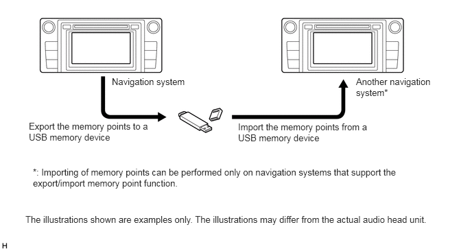
Memory points export/import function
The navigation system supports functions to export/import memory points. This function allows memory points stored in the radio and receiver assembly to be transferred to another navigation system (such as another radio and receiver assembly, etc.) via USB.
Memory points export/import procedure
DIAGNOSIS
For details on the procedure required to enter the Service Menu screen, refer to the Repair Manual.