A25A-FKS COOLING WATER PUMP INSTALLATION
CAUTION / NOTICE / HINT
- NOTICE:
-
This procedure includes the installation of small-head bolts. Refer to Small-Head Bolts of Basic Repair Hint to identify the small-head bolts.
-
Click hereGeneral>INTRODUCTION>REPAIR INSTRUCTION>PRECAUTION
PROCEDURE

 16323
1.INSTALL ENGINE WATER PUMP ASSEMBLY (WATER INLET HOUSING)
Install a new gasket to the engine water pump assembly (water inlet housing).
- HINT:
-
Be sure to clean the contact surfaces.
Install the engine water pump assembly (water inlet housing) to the cylinder block assembly with the 4 bolts.
- Torque:
- 43 N*m (438 kgf*cm, 32 ft.*lbf)
Connect the engine water pump assembly (water inlet housing) connector.
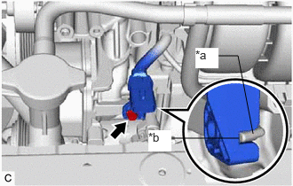
| *a | Protrusion |
| *b | Cutout |
Align the protrusion of the engine water pump assembly (water inlet housing) with the cutout in the sensor wire clamp.
Using an 8 mm socket wrench, connect the sensor wire to the engine water pump assembly (water inlet housing) with the bolt.
- Torque:
- 10 N*m (102 kgf*cm, 7 ft.*lbf)
Connect the sensor wire connector.
16031
2.INSTALL WATER INLET WITH THERMOSTAT SUB-ASSEMBLY