RM33A0E
_56
Audio / Visual / Telematics
_065374
NAVIGATION / MULTI INFO DISPLAY
_0328084
NAVIGATION ANTENNA
G
NAVIGATION / MULTI INFO DISPLAY NAVIGATION ANTENNA INSPECTION
PROCEDURE

 86860
1.INSPECT NAVIGATION ANTENNA ASSEMBLY
a.
Check that the navigation antenna assembly cable is properly installed and does not have any sharp bends, pinching or loose connections.
b.
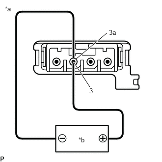
1.615,1.25 2.271,0.698
true
1.552,1.302 1.906,1.844
true
0.104,0.104 0.375,0.323
0.271,0.219
10
false
*a
1.667,2.885 1.875,3.063
0.208,0.177
10
false
*b
2.313,0.604 2.583,0.823
0.271,0.219
10
false
3a
1.896,1.844 2.167,2.063
0.271,0.219
10
false
3
| *a | Component without harness connected
(Navigation Antenna Assembly) |
| *b | Voltage Applied between Terminals |
Current consumption check:
i.
Measure the current consumption according to the value(s) in the table below.
- Standard Current:
Tester Connection Condition Specified Condition 3 (core) - 3a (shield) 4.2 to 5 V applied between terminals 3 and 3a 10 to 30 mA
- NOTICE:
-
Do not apply 6 V or more between terminals 3 and 3a.
- HINT:
-
If a stable power supply is not available, connect 4 nickel-metal hydride batteries (1.2 V each) or equivalent in series.