RM33A0E
_51
Engine / Hybrid System
_065326
2AR-FE EMISSION CONTROL
_0328633
PURGE VALVE
A
2AR-FE EMISSION CONTROL PURGE VALVE INSTALLATION
PROCEDURE

 25860
1.INSTALL PURGE VALVE (PURGE VSV)
a.
1.01,1.688 1.24,1.688
1.24,1.688 1.594,1.938
true
0.667,2.458 0.896,2.458
0.896,2.458 1.135,2.26
true
1.333,3.823 1.76,3.969
1.76,3.969 1.76,4.208
true
0.823,1.594 1.031,1.792
0.208,0.198
10
true
*1
0.479,2.385 0.688,2.583
0.208,0.198
10
true
*2
0.375,0.917 0.635,1.125
0.26,0.208
10
false
*a
0.969,1.302 1.198,1.5
0.229,0.198
10
false
*b
1.26,0.25 1.5,0.458
0.24,0.208
10
false
*c
2.594,1.302 2.813,1.521
0.219,0.219
10
false
*d
2.594,4.396 2.813,4.625
0.219,0.229
10
false
*e
1.677,4.198 1.917,4.438
0.24,0.24
10
false
*g
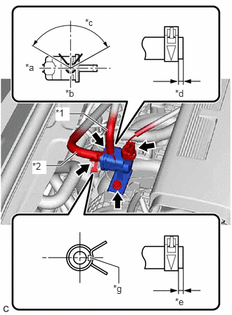
| *1 | No. 1 Fuel Vapor Feed Hose |
| *2 | No. 2 Fuel Vapor Feed Hose |
| *a | Front |
| *b | RH Side |
| *c | 120° |
| *d | 2 to 7 mm (0.0787 to 0.276 in.) |
| *e | 4 to 9 mm (0.157 to 0.354 in.) |
| *g | Paint Mark |
Install the purge valve (purge VSV) to the purge VSV bracket with the bolt.
- Torque:
- 10 N*m (102 kgf*cm, 7 ft.*lbf)
b.
Connect the No. 2 fuel vapor feed hose to the purge valve (purge VSV) and slide the clip to secure it.
- HINT:
-
Engage the clip within the area shown in the illustration.
c.
Connect the No. 1 fuel vapor feed hose to the purge valve (purge VSV) and slide the clip to secure it.
- HINT:
-
Engage the clip within the area shown in the illustration.
d.
Connect the purge valve (purge VSV) connector.