U761E AUTOMATIC TRANSMISSION / TRANSAXLE AUTOMATIC TRANSAXLE SYSTEM Transmission Control Switch Circuit
DESCRIPTION
When the shift lever is in S and moved toward "-" or "+", it is possible to select different shift ranges (S1 to S6).
Moving the shift lever toward "+" increases the shift range by one, and moving the shift lever toward "-" decreases the shift range by one.
WIRING DIAGRAM
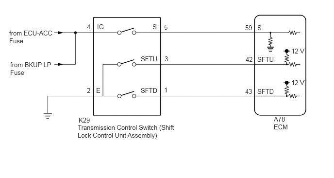
CAUTION / NOTICE / HINT
- NOTICE:
- ·
Inspect the fuses for circuits related to this system before performing the following procedure.
·Perform registration and/or initialization when parts related to the automatic transaxle are replaced.
Click hereDrivetrain>U761E (AUTOMATIC TRANSMISSION / TRANSAXLE)>AUTOMATIC TRANSAXLE SYSTEM>PRECAUTION
PROCEDURE
Connect the GTS to the DLC3.
Turn the engine switch on (IG).
Turn the GTS on.
Enter the following menus: Powertrain / Transmission / Data List / Shift SW Status (S Range).
According to the display on the GTS, read the Data List.
- Powertrain > Transmission > Data List
-
Tester Display Measurement Item Range Normal Condition Diagnostic Note Shift SW Status (S Range) S mode select switch status ON or OFF ·ON: Shift lever in S, "+" or "-"
·OFF: Shift lever not in S, "+" or "-"
-
- Powertrain > Transmission > Data List
-
Tester Display Shift SW Status (S Range) - 50003 373 27
- Result:
Result Proceed to Data List value is normal A Data List value is not normal B
A
B
Connect the GTS to the DLC3.
Turn the engine switch on (IG).
Turn the GTS on.
Enter the following menus: Powertrain / Engine / Data List / Sport Shift Up SW and Sport Shift Down SW.
According to the display on the GTS, read the Data List.
- Powertrain > Engine > Data List
-
Tester Display Measurement Item Range Normal Condition Diagnostic Note Sport Shift Up SW Sport shift up switch status ON or OFF ·ON: Shift lever held in "+"
·OFF: Shift lever not held in "+"
- Sport Shift Down SW Sport shift down switch status ON or OFF ·ON: Shift lever held in "-"
·OFF: Shift lever not held in "-"
-
- Powertrain > Engine > Data List
-
Tester Display Sport Shift Up SW Sport Shift Down SW - 50003 372 26,25
- Result:
Result Proceed to Data List values are normal A Data List values are not normal B
A
B
Disconnect the K29 transmission control switch connector.
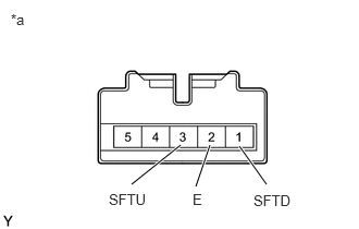
| *a | Component without harness connected
(Transmission Control Switch (Shift Lock Control Unit Assembly)) |
Measure the resistance according to the value(s) in the table below.
- Standard Resistance:
Tester Connection Condition Specified Condition 3 (SFTU) - 2 (E) Shift lever held in "+" (Up shift) Below 1 Ω Shift lever not held in "+" (Up shift) 10 kΩ or higher 1 (SFTD) - 2 (E) Shift lever held in "-" (Down shift) Below 1 Ω Shift lever not held in "-" (Down shift) 10 kΩ or higher
- Result:
Proceed to OK NG
OK
NG
Disconnect the K29 transmission control switch connector.
Measure the resistance according to the value(s) in the table below.
- Standard Resistance:
Tester Connection Condition Specified Condition K29-2 (E) - Body ground Always Below 1 Ω
- Result:
Proceed to OK NG
OK
NG
Connect the K29 transmission control switch connector.
Disconnect the A78 ECM connector.
Measure the resistance according to the value(s) in the table below.
- Standard Resistance:
Tester Connection Condition Specified Condition A78-42 (SFTU) - Body ground Shift lever held in "+" (Up shift) Below 1 Ω Shift lever not held in "+" (Up shift) 10 kΩ or higher A78-43 (SFTD) - Body ground Shift lever held in "-" (Down shift) Below 1 Ω Shift lever not held in "-" (Down shift) 10 kΩ or higher
- Result:
Proceed to OK NG
OK
NG
Disconnect the K29 transmission control switch connector.
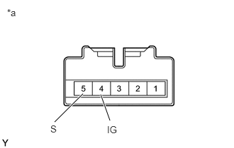
| *a | Component without harness connected
(Transmission Control Switch (Shift Lock Control Unit Assembly)) |
Measure the resistance according to the value(s) in the table below.
- Standard Resistance:
Tester Connection Condition Specified Condition 4 (IG) - 5 (S) Shift lever in S, "+" or "-" Below 1 Ω Shift lever not in S, "+" or "-" 10 kΩ or higher
- Result:
Proceed to OK NG
OK
NG
Disconnect the K29 transmission control switch connector.
Turn the engine switch on (IG).
Measure the voltage according to the value(s) in the table below.
- Standard Voltage:
Tester Connection Condition Specified Condition K29-4 (IG) - Body ground Engine switch on (IG) 11 to 14 V
- Result:
Proceed to OK NG
OK
NG
Disconnect the K29 transmission control switch connector.
Disconnect the A78 ECM connector.
Measure the resistance according to the value(s) in the table below.
- Standard Resistance:
Tester Connection Condition Specified Condition A78-59 (S) - K29-5 (S) Always Below 1 Ω A78-59 (S) or K29-5 (S) - Body ground and other terminals Always 10 kΩ or higher
- Result:
Proceed to OK NG
OK
NG