K120 CVT PARK / NEUTRAL POSITION SWITCH REMOVAL
CAUTION / NOTICE / HINT
The necessary procedures (adjustment, calibration, initialization or registration) that must be performed after parts are removed and installed, or replaced during park/neutral position switch assembly removal/installation are shown below.
| Replaced Part or Performed Procedure | Necessary Procedure | Effect/Inoperative Function when Necessary Procedure not Performed | Link |
|---|---|---|---|
|
*1: w/ Smart Entry and Start System *2: w/o Smart Entry and Start System |
|||
| Battery terminal is disconnected/reconnected | Perform steering sensor zero point calibration | Lane Tracing Assist System | ( ) |
| Pre-collision System | |||
| Memorize steering angle neutral point | Parking Assist Monitor System | ()
|
|
| Panoramic View Monitor System | ()
|
||
| Replacement of ECM | Perform Vehicle Identification Number (VIN) or frame number registration | MIL comes on | ()
|
| Perform code registration (Immobiliser system) | Engine start function | See Service Bulletin for the registration method | |
| Replacement of ECM*1 | Perform code registration (Immobiliser function) | ·
Wireless door lock control system ·
Smart Entry and Start System (for Entry Function) ·
Smart Entry and Start System (for Start Function) ·
Steering lock function |
See Service Bulletin for the registration method |
| Replacement of ECM*2 | Perform code registration (Immobiliser function) | ·
Wireless Door Lock Control System ·
Engine start |
See Service Bulletin for the registration method |
PROCEDURE

 1.REMOVE BATTERY
89661
2.REMOVE ECM
74404A
3.REMOVE BATTERY CLAMP SUB-ASSEMBLY
33820B
4.DISCONNECT TRANSMISSION CONTROL CABLE ASSEMBLY
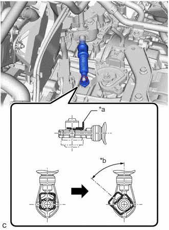
| *a | Clip |
| *b | 45° to 60° |
While disengaging the clip as shown in the illustration, disconnect the transmission control cable assembly from the transmission control shaft lever together with the clip.
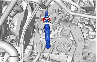
Remove the clip and disconnect the transmission control cable assembly from the No. 1 transmission control cable bracket.
84540
5.REMOVE PARK/NEUTRAL POSITION SWITCH ASSEMBLY
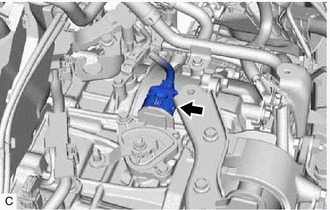
Disconnect the park/neutral position switch assembly connector.
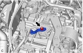
Remove the nut, washer and transmission control shaft lever from the manual valve lever shaft.
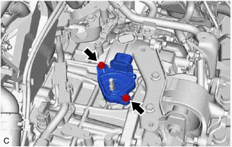
Remove the 2 bolts and park/neutral position switch assembly from the transaxle case sub-assembly.
- NOTICE:
-
Before removing the park/neutral position switch assembly, remove any dirt or rust on the installation portion of the manual valve lever shaft. Be sure to remove the park/neutral position switch assembly straight along the manual valve lever shaft while being careful not to deform the plate spring that supports the manual valve lever shaft. If the plate spring is deformed, the park/neutral position switch assembly cannot be reinstalled correctly.