K120 CVT SHIFT LEVER DISASSEMBLY
PROCEDURE

 35974
1.REMOVE LOWER POSITION INDICATOR HOUSING
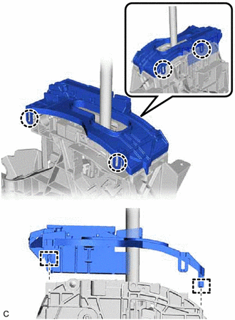
Disengage the 4 claws and 2 guides to remove the lower position indicator housing from the shift lock control unit assembly.
- NOTICE:
-
Do not damage the lower position indicator housing.
35978
2.REMOVE SHIFT POSITION INDICATOR
- HINT:
-
Perform this procedure only when replacement of the shift position indicator is necessary.
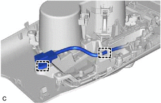
Disengage the 2 clamps to disconnect the wire harness.
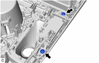
Remove the 2 screws.
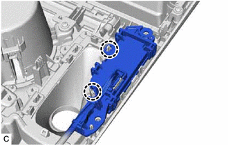
Disengage the 2 claws and remove the shift position indicator from the rear upper console panel sub-assembly.
35906
3.REMOVE INDICATOR LIGHT WIRE SUB-ASSEMBLY
- HINT:
-
Perform this procedure only when replacement of the indicator light wire sub-assembly is necessary.
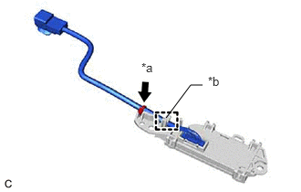
| *a | Tie Band |
| *b | Guide |
Remove the tie band.
Disengage the guide to disconnect the indicator light wire sub-assembly.
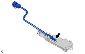
Disconnect the indicator light wire sub-assembly connector to remove the indicator light wire sub-assembly from the shift position indicator.
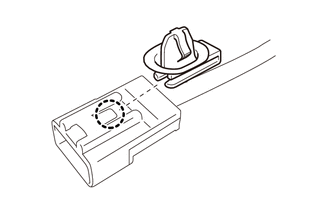
Disengage the claw to remove the clamp from the indicator light wire sub-assembly.
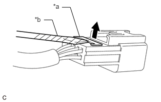
| *a | Secondary Lock |
| *b | Protective Tape |
Using a screwdriver with its tip wrapped with protective tape, release the secondary lock.
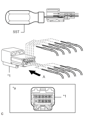
| *1 | Connector Housing |
| *a | View A |

|
Shift Position Indicator Terminal |
Using SST, release the locking lug of each terminal and remove the terminal from the connector housing.
- SST
- 09991-00510
- NOTICE:
-
Before removing the terminals, make a note of the color of each wire and position where its terminal is installed.